1990 90 HP Charging Issue

KRH1326

Chief Petty Officer
Joined
Sep 22, 2007
Messages
491
hi everyone... been a while since I was in these forums.

im not a Merc guy, and this issue is driving me crazy. It’s my son’s, new to him, 1990 90 HP. It looks like serial number 0C272485.

it has a low amp stator and a rectifier... no regulator. Simple three terminals on rectifier. The ++ term is for red wire to batt on starter solenoid. The other two each get a yellow stator wire, and one brown for tach.
I tested the stator as per book. Continuity from yellow to yellow wires.... aok. No continuity from either yellow to good ground... aok.
i tested the rectifier as per book and found it faulty, by ohmmeter. I bought a new quicksilver rectifier, and installed it. No sign of any charging. I pulled it, and tested it and it comes up faulty per the book, by ohmmeter testing. I reinstalled it, just so my son can still run boat... and he tells me that he seems to be maintaining 12.1 -12.2 volts, via the little voltmeter/ phone charger, I had installed for him.
ok... I get a chance today to investigate further. I pull and retest the rectifier.. shows faulty as per book and ohmmeter. I take it with me, back to dealer, and he tests it, as faulty. He actually gives me another new one. For the heck of it, in the parking lot I test it. It too comes up faulty. I know it’s a different one because I opened the package, and my “old one” was still on the counter. I show him, and he tests it. My vision is poor and couldn’t see his meter numbers, but he says it checks out. Ok so I think there could be something wrong with my meter.
I go back to mooring, and install the second rectifier. I double checked the stator wires and ground readings, just for fun. Still shows aok.
fire up motor and it still seems to be trying to maintain that 12.1 / 12.2 voltage. I could see meter drop to 11 with the starter engaged. Once running it returns to 12, then with high idle it comes back up to 12.1
I play with the tilt/ trim and meter drops into 11’s. Then comes back up to 12.1 volts with high idle. I attempt the test, from the book, of placing ammeter inline between rectifier ++ term and the disconnected red wire to starter solenoid/ batt..... I cant read any amperage !
i pull of all wires on rectifier and test it for the hundredth time. Still checks as faulty.

so here I am , asking for help, lol
is my test meter failing ?
does this Merc low amp , non-regulating stator really only maintain about12.1 / 12.2 volts ? Am I possibly missing something? Would love some input before I buy another rectifier, from a different place , lmao
 

KRH1326

Chief Petty Officer
Joined
Sep 22, 2007
Messages
491
I did just use a small battery, a 12v test light, and my meter as an ammeter. It worked as I expected... showing some current...
 

Texasmark

Supreme Mariner
Joined
Dec 20, 2005
Messages
14,665
Pull the yellow wires from the rectifier and run the engine up to 2000 rpm with your Digital Multi Meter leads across the wires and range set to 20 VAC....Volts Alternating Current. By the time you hit 1000 rpms you should get a solid reading above 13v and as you increase the rpms the voltage should rise. If that checks the stator seems to be ok under a "static" load.

The rectifier is a full wave bridge consisting of 4 diodes. When one of the stator wires is + with respect to the other, it forward biases a diode to the rectifier case (D1)....ground, and the opposite lead forward biases a diode connected to the red output terminal (D2). When the stator input reverses polarity (as the magnet on the flywheel passes the respective induction coil in the stator), the inputs do the same thing but with (D3) connected to ground and (D4) connected to the red output.

By connecting between a stator input (stator wires disconnected) and ground and the other stator input and + out (testing your rectifier module) you can check diodes D1 and D2 and reversing your leads on the stator inputs you can check D3 and D4.

I really find it hard to believe that in today's market you will find a new bridge rectifier bad out of the box....unless it wasn't the item shipped from the manufacturer, originally in the box. I'd suspect my instrumentation first, or test methodology.
 

KRH1326

Chief Petty Officer
Joined
Sep 22, 2007
Messages
491
I thank you for that. Will try the stator leads, while running, tomorrow
 

KRH1326

Chief Petty Officer
Joined
Sep 22, 2007
Messages
491
Bought a good quality Klein multimeter, to back up my original findings. Every test result, listed in OP is true and accurate.
that means my new quicksilver rectifier is indeed faulty.
I checked ac voltage at two stator leads, as you stated. Had 50-60VAC at a high idle across the two leads. I checked each lead to ground, and had 20-30 vac at each.
Going to try another new rectifier ( bringing meter and will test before buying, lol) from different vendor. And it will be a Sierra Marine one, would rather get CDI , but not in stock anywhere near me.
 

KRH1326

Chief Petty Officer
Joined
Sep 22, 2007
Messages
491
Yes, a small one, just forward of rectifier... butnone of the circuits being tested, pass thru that. Two yellow stator leads go directly to the two terminals on rectifier, a red goes directly to batt side of starter solonoid, and there is a tach wire that goes on one of the stator posts, that goes directly to control harness, as per wiring diagram, in book.
 

sam am I

Commander
Joined
Jun 26, 2013
Messages
2,169
Something is fishy here.......Not sure that many rectifiers (diode bridge) could all be bad! If you trust they're good from the parts house (at least one so far), it's hard to smoke them and not know it, diodes usually pop and smoke, crack and stink (even through potting) if you hook them up into a circuit wiring where they are blowing up. e.g., If your boat was somehow smoking them upon install, you'd know it instantly.......

Do you have a "diode test" setting on your meters? w/o this setting, the forward break over current requirement (esp larger rec diodes) of the diode's pn junction is such that the current of a meter on "ohms" scale isn't always sufficient to forward bias the diode. i.e., the readings are a bit flaky and subjective depending on temp of the diode, the current supplied by a given ohm scale and the meter used.

On "diode test", there is a more of a "standard" and you'll see a much more definitive reading, should see around 0.5V, 0.6V per diode (Si) junction.

Also, the metal pad part of the rectifier assembly is the ground terminal of the rectifier. Make sure this metal pad mounting/grounding properly to the block (which should be grounded to the batt neg as well) else it won't charge.

Also...

1)
No continuity from either yellow to good ground... aok.

2)
I checked each lead to ground, and had 20-30 vac at each.

If neither yellow wire is referenced to ground (1), how could then you truly measure (2) either yellow from that same ground they aren't connected too? I'm not sure about something here is I guess what I'm saying.

They(yellow wires) should be floating/isolated from ground, #1 is correct BUT, I think #2 is suspect and perhaps points to an/the issue.

But ya have to ask yourself when you made it.....How is the non-ground referenced AC signal able to be measured from the ground it's not reference too? Right?

Maybe just a false/nonsensical reading is all.
 
Last edited:

KRH1326

Chief Petty Officer
Joined
Sep 22, 2007
Messages
491
That new Sierra rectifier, did the trick.
Tested it at store before purchase. Installed on mooring. In just 45 minutes of putting around the harbor, battery voltage climbed from 12.1 to 12.9
i do understand that this is just an unregulated 9 amp stator, and not to expect whopping charge from it...

Sam I am, I think I misstated or you misread.. doesn’t matter now :) The test procedure from the book, is to check continuity through both yellow stator leads, which I did and had continuity, which is good. Then to check for continuity from each lead, to ground... which would indicate a short. There was no continuity, which is good, and stator passed the book’s procedures.
Then TexasMark suggested to test VAC on running motor. To test for the output from the two stator leads, which I did and posted the 50-60 vac readings. I then tested each lead to ground, running, and posted the 20-30 VAC results. It’s like having two phase 220 feed..the two hot wires will read 220, while either one to ground, will give you 110 volts, just like the two phase power, feeding your house.
My first meter, on ohm settings was enough to read through the diodes... but as suggested, I doubted my instrumentation, and purchased a higher quality Klein meter, which has, and I utilized, a dedicated diode setting, to confirm all of my first readings.

neither had and kind of pop, or smoke , or stink. That would have shown easily, as I was right there, with open cowling expecting to see a charging system. Neither produced any dc voltage, right out of the box. The dealer was surprised as was I. He is speculating a batch of bad parts or perhaps a damaged shipment.. something...

thanks all for the help
 
Last edited:

sam am I

Commander
Joined
Jun 26, 2013
Messages
2,169
He is speculating a batch of bad parts or perhaps a damaged shipment.. something...

Weird having so many bad, glad all is well.........


And, yes, sorta.....

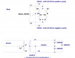
You can measure your houses 120VAC on each AC leg because your house's pole transformer has a center tapped secondary that runs to earth/neutral and then ran to your breaker box along with L1 and L2. Hence 240VAC between both L1 and L2 legs or 120VAC from earth/neutral to each leg L1/2 leg and neutral....See "House" below.

The stator coil(just like the pole transformer secondary cept perm mag primary) on your/my boat is isolated from ground because it's not center tapped there/anywhere, hence your "open/no continuity to ground".

The bridge rectifier is allowing and this is my mistake, (age thing I reckon these days) apologies. I forgot to consider electrically, how the full wave bridge allows the/a meter to ground reference one diode (see Vf D3 and Vf D4) junction below the AC side and measure the half cycle amplitude.

If you remove the rectifier, you should measure essentially 0V from either of the L1 or L2 legs back to ground because you've removed the diode reference to ground but still, you'd have the 20VAC between L1 and......... See "Boat" below.


Click image for larger version  Name:	FW Bridge.jpg Views:	1 Size:	131.0 KB ID:	10794225
 
Last edited:

Texasmark

Supreme Mariner
Joined
Dec 20, 2005
Messages
14,665
As your battery takes on a charge the load on the stator will drop and the voltage will rise. Unregulated rectifiers run 16v when battery is fully charged, more or less.

Glad you got it fixed. Amazing you had so many simple devices bad.
 
Top