1986 Suzuki DT40 Help Identifying Electrical Component

OldButSlow

Cadet
Joined
Jan 23, 2021
Messages
7
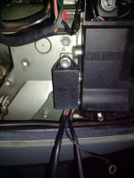
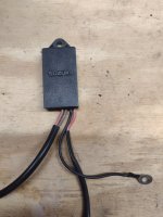
I bought an 86 DT40 (with tilt, remote steer, electric & pull start) to restore and lots of wiring is disconnected, stripped back or has probe hole poked through. I purchased the factory service manual and got everything identified, routed and connected, except... I can't seem to locate this component on the wiring diagrams to determine it's function or proper connection. And trying to identify faded wire colors being colorblind is no picnic either. It's location beside the CDI holder makes me suspect it's input to the CDI. But the two open female bullet connectors remaining on the CDI are showing not used (empty) on my model's wiring diagram (the pink & solid blue CDI wires). It appears to have at least one diode inside it, based on my tests with multi-meter. The part number is also smudged off of the back. Anybody know the function/connectivity of this component? Thanks. IMG_20220306_224012830.jpgIMG_20220306_224133063.jpg
 

boscoe99

Lieutenant Commander
Joined
Aug 22, 2013
Messages
1,997
Is the rectifier installed on the motor in addition to this mysterious part?

My guess is that it might be an upgraded rectifier or perhaps a rectifier/regulator. But...
 

OldButSlow

Cadet
Joined
Jan 23, 2021
Messages
7
Good thought. It does have a rectifier installed on the other side, but diode checks indicate it's a simple rectifier, not rectifier/regulator. Wiring diagram does show a separate voltage regulator as an option, but the photos I find of the part # for it and number of wires are completely different. I think I might hook it up to a 12 volt power power supply and see what, if anything happens to the other two non-ground wires as I energize the third.
 

racerone

Supreme Mariner
Joined
Dec 28, 2013
Messages
38,089
Where do the wires from this box go ?-----Careful with the " lets see what happens " approach.------It could be part of an idle speed circuit.----Exact model # is ?
 
Last edited:

OldButSlow

Cadet
Joined
Jan 23, 2021
Messages
7
1986 DT40TC. Appears to be the "VH" model according to the wiring diagrams. I just located a second wiring diagram further into the manual in that does include the one wire that appears to be fed to this black mystery box from the boat side wiring harness (but diagram also doesn't show the box itself). It's the gray wire that also supplies key on power (12v+) to the alarm buzzer (buzzer appears to be ground side switched by temp sensor in head). Also, I reconnected the black ground wire to the block and it shows continuity to one of the two pink wires coming out of the box. That pink wire was probably connected to the pink female bullet terminal on the CDI (based on the shape the wire had taken). Looks like the other pink wire (no continuity to ground) might share the 12V+ circuit from the tilt switch to the down tilt solenoid. I'm basing that on how the wires want to lay in the bottom cowl and open female bullet connector terminals. I'm trying to see the possible logic behind a sensor that might be taking 12V+ input when the down tilt circuit is energized, added to constant 12V+ key on power and output something to the CDI that it needs to know. The engine cranks, idles and runs good on the stand without the black box hooked up to anything. So I suspect it's a monitor circuit. But the logic isn't apparent to me and I am leery of hooking it up wrong since it possibly inputs to the CDI. Thanks for helping me think through this.
 
Top