Ok, thank you, will test in the AM. Appreciate the response!If it runs correctly you diagnosed a bad rectifier and will need to replace it.
Ok pulled those 2 wires, motor didnt start, put those 2 wires back on and motor now still will not start.If it runs correctly you diagnosed a bad rectifier and will need to replace it.
Have no spark at all now.If it runs correctly you diagnosed a bad rectifier and will need to replace it.
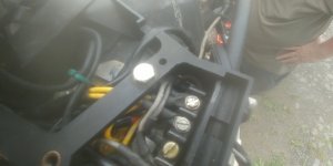
I unscrewed the 2 yellow wires (one yellow with white line) and motor did not start, then i reconnected them and now am still left with no spark. That's the 2 wires, one side to stator one side to plastic block tired to rectifier. I removed them at the screw on the block.Sounds like you unplugged wires from stator to pack. The yellow wires under the plastic cover held with fast screws are the one you need to remove.
Black wire on bolt for power pack is solid, will sand and reconnect.Make sure pack ground wire attached.
Good solid ground, still no spark.Make sure pack ground wire attached.
Ok, so its hard to tell what the actual color of the wires are, but look like orange/white line (O/W) and like a pink or off white with black like (W\B) then there is yellow/white (YW) and yellow (Y)Those wires purpose is to charge battery and a defective rectifier can cause stator to overheat. Need to ohm and DVA test stator as if might have went ahead and failed. Or timer base as they can come and go depending on temp.
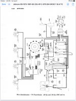
The diagram does not seem to match my motor. The wires def. Appeae to be yellow and yellow and white, and I only have 1 power pack. . .Might be of some troubleshooting help: https://www.cdielectronics.com/support/
and perhaps this for the rectifier/regulator: https://www.maxrules.com/graphics/omc/wiring/1985_90_115TnT.jpg
This would be for mine. Don't know if that changes anything.Might be of some troubleshooting help: https://www.cdielectronics.com/support/
and perhaps this for the rectifier/regulator: https://www.maxrules.com/graphics/omc/wiring/1985_90_115TnT.jpg
The brown wires give me 0v, at all times, and are the wires the have 589 Ω. And if those 2 yellow wires are connected to the rectifier, with the key on, they read 12v between them. This suggesting the rectifier is bad? I will redo the tests when then storm passes just to make sure.As stated no voltage on yellow wires from stator unless flywheel is turning and this will be AC voltage. Check voltage on brown wires from stator to pack .
As stated beforehand above, if you get DC voltage with key on engine off on either of the stator wires then the regulator/rectifier is bad.The brown wires give me 0v, at all times, and are the wires the have 589 Ω. And if those 2 yellow wires are connected to the rectifier, with the key on, they read 12v between them. This suggesting the rectifier is bad? I will redo the tests when then storm passes just to make sure.
Actually that was not stated above, ive asked the question, but it wasn't answered as to what having 12v there meant. I was told it shouldn't be there, but not what getting that reading actually means, or what it means is bad.As stated beforehand above, if you get DC voltage with key on engine off on either of the stator wires then the regulator/rectifier is bad.
The diodes in the device are one way gates, positive AC voltage only should be rectified towards the positive end of the electrical system. Positive Voltage/current that attempts to go the other way back to the AC stator should get blocked.
If you've spent time on basic electronics fundamentals (resisters, diodes, capactitors, transitors), drawing a diagram makes it a lot easier to check your work with the test specifications.
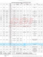
I do not have a meter with a peak freeze, but with meter set to read up to 500v, only gives me a visible result of 86v from brown wires while cranking. Not, sure if this is accurate to the DVA test. All the numbers on the blue line highlighted below come back in spec, with the exception of the brown wires, which as stated question my method.The only wire to have 12V should be the red on rectifier, the yellows will have no voltage with key on....if so as posted the rectifier is toast. Your ohn spec is close for th brown wir and with leads hooked to the browns only , cranking you should see 160-400V on meter with DVA adapter.