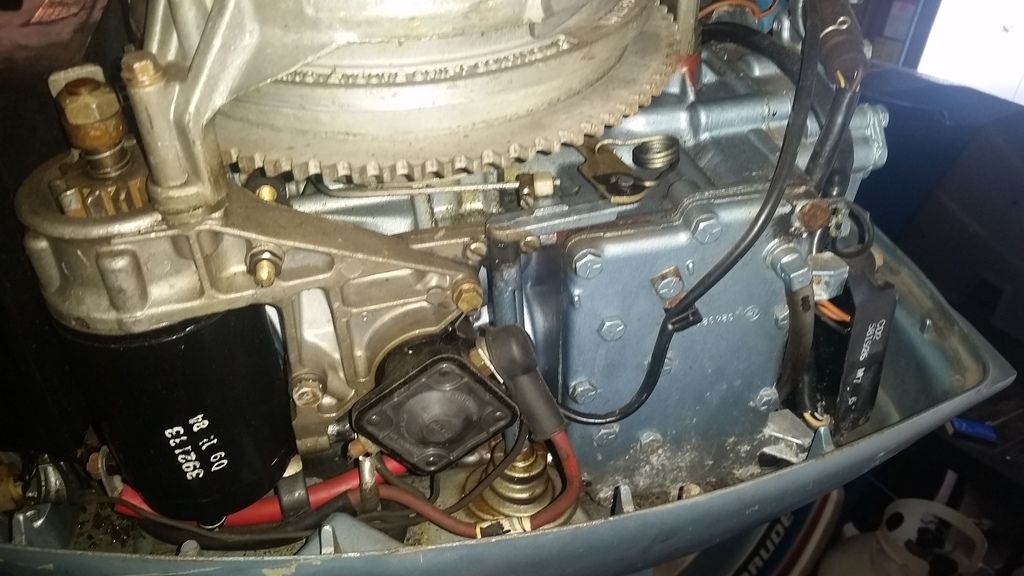
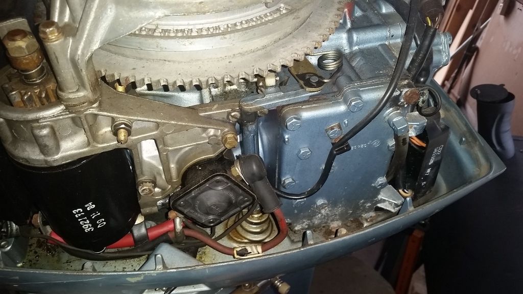
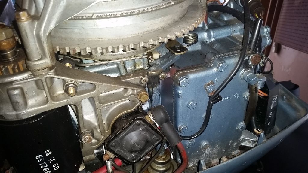
1980 Evinrude, 35 HP General Questions with pictures

UConnMRB

Petty Officer 2nd Class
Joined
Jul 18, 2014
Messages
119
I have a 1980 35 HP Evinrude that sat in a garage for 15 years without being run (was winterized before it was stored). She has good compression (about 115 on both cylinders) and after replacing the plugs, she fired right up after 2 pulls. I shut her down right after she started as I have not done any of the "awakening" steps that are needed. I have some general questions for the experts out there, as I know nothing about outboards other than what I have learned in my hours of reading on this site.

1) There is some surface rust on the flywheel and fuel filter housing. Is this an issue?
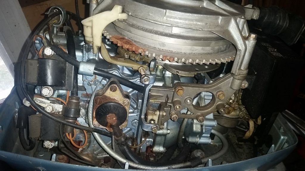
MotorCloseupNoCowl_zps3llc5ldy.jpg


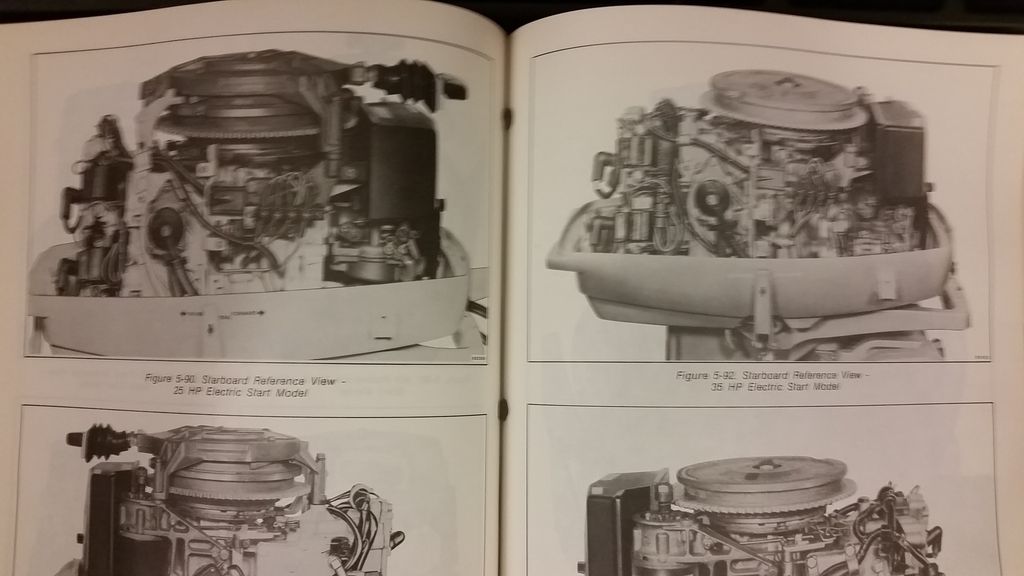
2) I bought the official Evinrude service manual for this motor. In that it references either a pull start model or an electric start model. This motor, however, has both options. Is it possible that Evinrude created some models that had both options, but didnt mention it in the manual? Some parts are different for the two versions. You can see in the manual that the 35 HP pic on the right does not have pull start option, yet the 25 HP electric on the left does have it. According to the serial number, this is a 35 HP.
c0e4195d-a4fd-4b39-8b34-8f0b6ae63fd3_zpsx8a4dukq.jpg


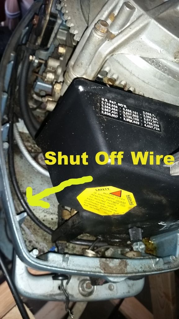
3) The push stop button is not working. There is a wire attached to the button but it leads to nothing, it is just laying there. The manual doesnt really describe how to hook it up. Does anyone know where that should go?
091ddaa8-3c0f-401c-9dc2-669c3cc8cebc_zpskgx8vma9.jpg


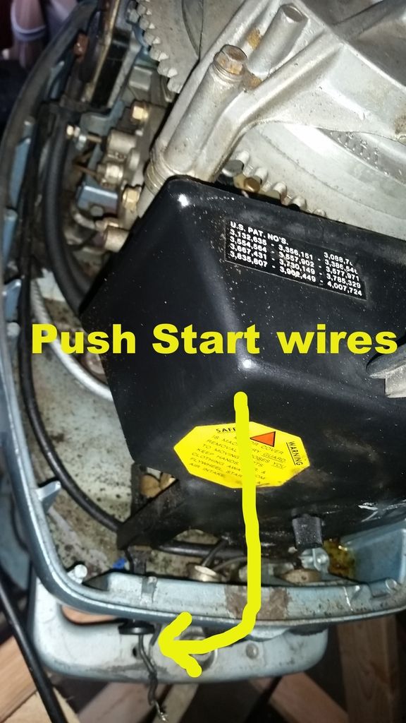
4) The push start button has been removed and the wire are just hanging out through the hole where the button was. I assume this is how it was wired to the ignition key. Does that sound right? Can I just rewire the ignition in the dash to those two wires and connect them?
b3eae025-5926-41b4-88f4-0887c936ce35_zpswj9lfe08.jpg


Thank you all for reading this. I am sure I will have more questions as I progress. I hope its warming up for everyone.
 

Chinewalker

Fleet Admiral
Joined
Aug 19, 2001
Messages
8,902
For the stop wires: One will go to the block for ground (which looks like it is, bottom coil, top bolt), and the other will go to the power pack via the 5-pin black plug at the pack (top of cylinder head).

For the push start - hard to tell as I don't know what you've got. You motor lacks a charging system (no rectifier visible), so any starter someone has added was done sometime between when it was new and now. No idea how complete the system added was. A full electric start system would include a starter solenoid mounted to the starter bracket. One wire from the push button would run to one post of the solenoid, and the other would run to the hot side of the solenoid.
 

UConnMRB

Petty Officer 2nd Class
Joined
Jul 18, 2014
Messages
119
Thanks for the reply Chinewalker. I guess I assumed the opposite, that someone added a pull start feature to the electric start model. I am not sure what to look for as far as the charging system (rectifier) as I am a novice. I do have a picture of the other side of the motor though, which shows the starter solenoid.

MotorCloseupNoCowl2_zpshzzeickz.jpg
 

UConnMRB

Petty Officer 2nd Class
Joined
Jul 18, 2014
Messages
119
I forgot I have the service manual with me at work. You are correct, the manual mentions how to remove the rectifier and replace it and I dont see any sign of a terminal board. Sorry for be so new to this, but what does not having a rectifier mean for me?
 

racerone

Supreme Mariner
Joined
Dec 28, 2013
Messages
38,045
It means that there is no battery charging system on the motor.
 

racerone

Supreme Mariner
Joined
Dec 28, 2013
Messages
38,045
It means that there is no battery charging system on the motor.-------There is a collar on the thin rod that goes to the back of the motor.---You may need to check the adjustment of that collar.
 

UConnMRB

Petty Officer 2nd Class
Joined
Jul 18, 2014
Messages
119
Thanks racerone. I am not locating the collar and I am not sure what I checking for as far as an adjustment. So with no batter charging system on the motor, I should run 2 batteries? One as a starting battery and one for electronics? I dont plan on running much for electronics.
 

racerone

Supreme Mariner
Joined
Dec 28, 2013
Messages
38,045
Post # 3 ---post another picture like that with the throttle control in the slowest idle position.
 

UConnMRB

Petty Officer 2nd Class
Joined
Jul 18, 2014
Messages
119
Pic #3 was with the throttle as low as it will go, here is another pic of it I just took:

20150409_163813_zps7nnfkgjz.jpg


Just for reference I then set it to WOT:

20150409_163830_zpsnkci8f2d.jpg


Thanks again for everyone's help/interest/views.
 

racerone

Supreme Mariner
Joined
Dec 28, 2013
Messages
38,045
That adjustable collar to the left of the spring may not be adjusted correctly.---Refer to your manual for adjustment of that.----Folks often adjust that because it " looks to be wrong " when it is in fact adjusted correctly.
 

UConnMRB

Petty Officer 2nd Class
Joined
Jul 18, 2014
Messages
119
oh ok, I will look into it. Thanks for the heads up. I am finding that owning a manual is worth every penny, especially to someone trying to learn all they can about their motor and motors in general.
 

bonz_d

Vice Admiral
Joined
Apr 22, 2008
Messages
5,276
Is this a tiller engine?
I have no idea what that wire is that is coming out of the front, Picture 4 where that wire is at least on the 35hp I had that black knob is the manual choke. I also do not see a wire loom or the red cannon plug for a remote starter.
 

racerone

Supreme Mariner
Joined
Dec 28, 2013
Messages
38,045
???????--------The pictures clearly show that it is a remote motor.-----No tiller.
 

UConnMRB

Petty Officer 2nd Class
Joined
Jul 18, 2014
Messages
119
I have a little tiller acceptor area right in front of starter. When the throttle moves so does the tiller port.
 

UConnMRB

Petty Officer 2nd Class
Joined
Jul 18, 2014
Messages
119
Its not in any of the pictures that I posted, its just out of sight on a few of them. I will take a pic or two tomorrow.
 

Chinewalker

Fleet Admiral
Joined
Aug 19, 2001
Messages
8,902
Your starter motor is dated from 1984, so that, at least, came from an '84 model. When it was added? Anyone's guess.

At the power pack plug, you should see one wire that's black with yellow tracer. That's the kill wire. Your kill switch should mate up to that wire. It'll be the at one of the corners of the three wire plug that also houses the orange wires. (I had previously stated it was a five pin plug - that was for a different year.)

The adjustable brass bit on the thin horizontal throttle rod definitely looks to be out of whack. It's usually about 1.5 inches from the end of the rod, and there't usually a tiny cotter pin or bit of paper clip through the end of that rod where the empty hole is.

It's not hard to add charging if you want it. PM me if you think you might want to go in that direction.
 
Last edited:
Top