1976 Mecruiser 351W Trim System

kenny nunez

Captain
Joined
Jun 20, 2017
Messages
3,290
You should not try turning the inner hex screw. That is a pressure regulator and to adjust it a pressure gauge is needed, the wrong setting will blow up the outer tubes of the rams.
You are right about the fitting change. Try connecting the system like I described. If you luck out and find a good reverse lock valve then it can be re-connected.
 

orttauq

Seaman
Joined
Aug 27, 2022
Messages
71
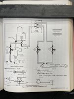
Definitely did not mess with the inner hex screw :) I did find the reverse lock valve NOS so I have that on its way and the reverse lock switch is installed. I am down to just sorting the routing of the hoses. I also now have the 2 service manuals for that year MC1 and found a 'test' diagram but not a 'working' diagram. Here is a pic of the page:

Photo Nov 17, 2 42 31 PM.jpg

I don't know what the one line is going up the left side of page is. Is it the 'working' down line? and the other Reverse Lock Test line is temp routing during testing that bypasses the rams alltogether ? What is the Adapter or Fittings box at the top? Is this the block mentioned that is under the gimbal ring?

Is this right for 'working' routing:
Pump 'Down' port to Sender | from sender to Reverse Lock Valve | Reverse Lock Valve to 'Down' Line to Adapter to "Down" port (aft) on ram
Pump 'Up' port to 'Up' line to Adapter to 'Up' port (forward) on ram

So if I have this right the trim sender is only on the 'Down' hydraulic circuit.

Thanks for all your help on this and I hope all this info helps others down the road.
 
Last edited:

kenny nunez

Captain
Joined
Jun 20, 2017
Messages
3,290
You got it. The line on the left goes to the “out” port on the reverse lock valve. Then it goes to the block on the bottom of gimbal housing.You just need the female 1/8” npt to 3/16” inverted flare plumbing fittings for the 3/16” inverted flare nuts. You could restore the low pressure lines but finding the female and male fittings might be hard. It is easier at this time to stick with the flare nut system.
 

orttauq

Seaman
Joined
Aug 27, 2022
Messages
71
Here is some useful info re: these older all metal trim pumps:
There are 4 o-rings between the reservoir base and the valve body on the bottom-part number is 25-48171. This same o-ring is used on the filler screw (10-79953q04) so you will need 5. The large o-ring for the reservoir to is valve body housing is 392-2937. As of this posting SeaWay Marine in Lynnwood, WA stocks them.
The reverse lock valve is 48165a5 (this number is for the valve that has the two screw holes for the switch) and the lockout switch is 46482a1; both of these are NLA so eBay is your best option. The Limit Stop Switch 45942a1 is NLA too but eBay is very limited on supply and $$ if listed. As with most all older Mercruiser part numbers these may have been superseded with new numbers.

 
Last edited:

kenny nunez

Captain
Joined
Jun 20, 2017
Messages
3,290
Just a suggestion. The “O” rings can be had at any auto store by matching them up. When the valve block is off put a straight edge across the bolt holes, most times the block is not flat. Just take a file and some Emory cloth to restore the flat surface.
 

orttauq

Seaman
Joined
Aug 27, 2022
Messages
71
Thanks, the o-rings from Seaway (OEM) are only $1.36 so no big deal there.
Yes, I did check the valve block and plan on running over both sides with surface grinder/stone. (have a client with a machine shop so I will let them do it)
 
Top