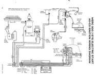
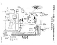
Ive checked the diagrams. I seem to have this right, but need an answer from someone more knowledgable than me. From the Mercontrol, I have Red, Black, Yellow, White, Salmon, Brown, Grey. Engine side, same colors. My question is about the white wire, specifically.
CDI says it is not used on the engine side. The other two relavent diagrams from maxrules and the service manual do not show a white wire on the engine side.
The way the control is set up, white seems to act as 12v for both the choke button and the tach lead. It shows the white wire present on the control side of the harness, marked as “F” and in the center pin position on the connector. However, in all the diagrams, thats it for the white wire. Just terminates in the harness connector.
It would seem that the matching white lead on the engine side would go to a 12v source, right? Not just for the tach, which there is also a brown lead for, but also for the choke? Should that be to the rectifier terminal with the red lead connected? Or should it be straight to the solenoid with the main red power wire (doesnt seem likely as then it would not be a switched power source).
Long post for a short answer, but Id rather lay out my full process now instead of getting the third degree later. I checked forums as best I could. Lots of wire related info, but mostly in regards to the tach.


