1975 85 hp vernitherm and relief valve

newboatfella

Recruit
Joined
Sep 23, 2009
Messages
5
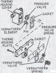
hello all, Ive taken apart thermo housing cover and plate to remove and clean and test vernitherm, valves and springs. My Johnson service manual says to place vernitherm spring, vernitherm valve and relief valve spring under thermohousing plate and secure with screws. Then place vernitherm element and pin along with the relief valve in thermo housing cover and secure. My problem is this is not the way it came apart. the vernitherm spring, valve and the relief spring and valve were installed behind the thermo housing plate. Only the vernitherm element and its pin were installed in the cover. A cutaway view on page 6-2 agrees withe way it came apart, as far as i can see. The engine runs ok on muffs but overheat buzzer went off about 2 minutes at idle in test tank. Really confused on this, can anyone help me.
 

ezeke

Supreme Mariner
Joined
Sep 19, 2003
Messages
12,532
Re: 1975 85 hp vernitherm and relief valve

The diagram is correct.

Make sure that the small holes that run though both gaskets and the thermo housing plate are clear.
 

Attachments

  • 1973 to 77 thermostat.JPG
    1973 to 77 thermostat.JPG
    77.5 KB · Views: 2

newboatfella

Recruit
Joined
Sep 23, 2009
Messages
5
Re: 1975 85 hp vernitherm and relief valve

im on it. going to take it apart and install it as per manual, an check all small passages. Thanks for your reply
 

newboatfella

Recruit
Joined
Sep 23, 2009
Messages
5
Re: 1975 85 hp vernitherm and relief valve

well i took it apart and found if i install the pressure spring behind the plate it doesnt even contact the pressure valve or extend beyond the plate. you dont even have to install the pressure spring before you secure the plate because you can pass the spring right thru the plate and seats in the adapter. it seems to make more sense with both pressure valve and vernitherm valve both spring loaded behind the plate. still confused. any thoughts
 
Top