1965 EVINRUDE sportfour 75hp

F_R

Honorary Supreme Mariner
Joined
Jul 7, 2006
Messages
28,226
So I have figured a few things out so far. My stator wires don't match the diagrams. I have two blacks and two reds but should have two yellows and a red and blue. I think I have it hooked up right finally but still won't start. I also ordered and received a new resistor wire and a new throttle cable which is unrelated but mine is a goner. Any suggestions on what else to try? How many volts should I get at the coil?
If you think you are confused, how about us? Stuff you are telling us just doesn't match. I can't think of any model with two black and two reds from the stator. Besides, the stator on your (supposedly) model has absolutely nothing to do with the spark. It functions solely as a 20A alternator to charge the battery.

It's time for you to post some pictures of just what you have.

EDIT: Voltage at the coil + should be approximately 12 if both sets of points are open and approximately 6-8 if one or both sets of points are closed.
 
Last edited:

F_R

Honorary Supreme Mariner
Joined
Jul 7, 2006
Messages
28,226
No Title

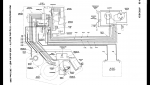
I don't have the 1965 diagram, but here is the 1966. It should be very similar and understandable by anybody experienced in outboard electrical systems.
 

Attachments

  • photo233766.jpg
    photo233766.jpg
    184.4 KB · Views: 0

Myomere

Seaman Apprentice
Thread starter
Joined
Apr 27, 2014
Messages
30
No Title

So the diagram I am using shows the resistor wire going to the coil and then inline with the voltage regulator. The stator was rewired at some point and my electrician at work found two bad wires. F_R the diagram you sent seems much better than the one I used but shows the wires being hooked up differently. Someone here helped me out and this is the diagram I have
 

Attachments

  • photo245161.png
    photo245161.png
    440.1 KB · Views: 0

Myomere

Seaman Apprentice
Thread starter
Joined
Apr 27, 2014
Messages
30
I added a bunch of pictures there of all of the wires I have coming from different components. Any insight would be helpful as the wiring was pretty butchered when I got the boat
 

Myomere

Seaman Apprentice
Thread starter
Joined
Apr 27, 2014
Messages
30
I also wanted to mention that I no longer have the original voltage gauge as it was completely rusted and destroyed So I hooked up the wire directly to the ignition switch. Not sure if that would cause issues
 

F_R

Honorary Supreme Mariner
Joined
Jul 7, 2006
Messages
28,226
Ah, so I see the reason for the incorrect wire colors. They are not the original wires. Man, all I can tell you is wire it up according to the diagram I posted. And when troubleshooting check circuits that apply. If the lights don't work in your bedroom, it would be a waste of time checking the fuses for the swimming pool pump. Don't confuse yourself with circuits that don't apply. For instance, you previously mentioned the stator which has nothing to do with the ignition system.
 

Myomere

Seaman Apprentice
Thread starter
Joined
Apr 27, 2014
Messages
30
So I just wired it based on your diagram and will try to start it and see. I wasn't getting spark and the previous diagram had different wires going in different directions
 

Myomere

Seaman Apprentice
Thread starter
Joined
Apr 27, 2014
Messages
30
Doesn't seem to want to start. The trouble is I don't know which wires coming from the stator go to the voltage reg and which ones go to the fuse.
 
Last edited:

jimmbo

Supreme Mariner
Joined
May 24, 2004
Messages
14,699
Don't worry about the stator at present time. Focus on the ignition system. Are you getting spark?
 

F_R

Honorary Supreme Mariner
Joined
Jul 7, 2006
Messages
28,226
First thing you need to check is the spark. No, I'm serious. Do you have spark coming out of the coil before the distributor? Unplug the spark wire from the coil and unscrew it from the distributor cap. Then plug it back into the coil and rig up a spark gap off the other end. Crank engine. Do you have spark across the gap, yes or no? If you do, it is ok up to that point, and your trouble is in the distributor cap or rotor. If you do not, then proceed with the next step.

Next step is check the voltages at the coil. Leave the spark gap rigged up. Check voltage at the coil (+) terminal with key on. Should be somewhere around 6-8V if one or both sets of the points are closed, or around 12V if both sets of points are open. If it passes, repeat but check it while cranking. Voltage should fluctuate as points open and close.

There are further tests, but let's get these basic ones out of the way first. There is no voo-doo in electricity, it was invented at the time of Creation and follows established rules.

BTW, before you even embarked on all this, you should have taken a look at the points. Are they clean and properly gapped?
 

F_R

Honorary Supreme Mariner
Joined
Jul 7, 2006
Messages
28,226
Y'know what? Since you have not identified the stator wires, you ought to disconnect them till you have established ignition spark. As we've said before, they have nothing to do with ignition spark anyway.
 

Myomere

Seaman Apprentice
Thread starter
Joined
Apr 27, 2014
Messages
30
So I get around 8 volts at the coil with ignition on. The points are new and the condenser as well as the primary coil wire as I ripped the first one. The points is where I have a question: should they close all the way and then at their open position they need to be gapped .020? When they're closed they need to touch?
 

Myomere

Seaman Apprentice
Thread starter
Joined
Apr 27, 2014
Messages
30
So I readjusted the points and still no spark. I disconnected the stator.
 
Top