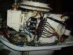
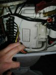
1965 Chrysler / West bend 50

Fabuglas

Seaman Apprentice
Joined
Oct 18, 2012
Messages
38
Hi, New to the site.
I have come to own a 1965 West Bend 500. I believe they called it a "Golden Shark" It is a 2 cyl, 2 stroke 50 hp. It seems to be all there. I would like to try and start it. The wiring harness out of the motor at the termination of the ignition switch, and the ignition switch itself, is a mess. Can anyone provide me with guidance on the correct type of ignition switch, how to wire the switch and what all 8 of the wires in the harness are for?

2 of the eight wires are noticeably thicker gauge then the other 6. All the wires in the harness are connected nicely to the terminal block on the motor, starter solenoid and starter.

I purchased a manual for all Chrysler outboards from the period. It is confusing because it covers multiple ignition systems and all HP models.

Does anyone have a diagram that indicates how the ignition harness should be wired out of the motor? I saw an old thread for a 45 HP West Bend but it did not indicate the year of that motor. The information provided stated:
1. Black - Battery negative (hot)
2. Red - Battery positive (ground)
3. Blue - Ignition ckt.
4. Yellow - Starter control ckt.
5. White - Tachometer
6. Orange - Heat indicator ckt.
7. Green - Choke control ckt.
8. Purple - Charge indicator ckt.

It seems odd to me that the red battery wire would be (ground) and the black battery would be (hot). This might get exciting if connected backwards.
Help!
 

Fabuglas

Seaman Apprentice
Joined
Oct 18, 2012
Messages
38
Re: 1965 Chrysler / West bend 50

The model # 50571
The serial # 3171
 

Frank Acampora

Supreme Mariner
Joined
Jan 19, 2007
Messages
12,004
Re: 1965 Chrysler / West bend 50

It will get more than exciting if you hook red to ground--and you will know right away. Red is always hot or positive and black is always ground.

NOW: Other wiring really depends upon ignition type. No matter what type ignition, orange is always heat indicator, yellow is always start and green is always choke. Typically purple is off the AC side of the rectifier and is not used.

If the engine is magneto ignition, blue and white are attached to the two lamp cord type wires (black or brown) coming from under the flywheel. At the ignition switch blue and white are attached to the two "M" terminals. This is the stop circuit. Additionally, white can be used for tachometer signal. Magneto ignition is self energising. When the switch is off, the two "M" terminals are in continuity. The points under the flywheel are shorted to each other and the magneto will not generate the high voltage to the sparkplug.
This ignition will usually not have an alternator so the battery must be charged at home.

If the ignition is battery, points, and coils, The coils will be mounted either on the side of the engine or attached to the slanted part of the head. This ignition will have an alternator and rectifier.

Blue is attached to the "I" terminal on the switch and the POS terminal of each coil. A white wire runs from the neg terminal of each coil up under the flywheel to the matching set of points. The white wire in the big cable is again used for tachometer signal. No Tach? Just don't use the wire.

With the switch on: Power runs from the blue wire to the coils. With the points closed, this power is allowed to pass through the coil and to ground. With points open, power is interrupted and the coil generates a high voltage pulse to the sparkplug.
 

Nordin

Commander
Joined
Jun 12, 2010
Messages
2,544
Re: 1965 Chrysler / West bend 50

Frank and all others, early Chryslers (WestBend) before 1965 with battery ign. had positive earth.
They were wired "backwards". It seems odd but they were wired as old english cars with Lucas system. Here in Sweden we call Lucas as " The man that invented the darkness"
SO: Fabuglas your information about the wiring is correct.
 

Fabuglas

Seaman Apprentice
Joined
Oct 18, 2012
Messages
38
Re: 1965 Chrysler / West bend 50

Frank
Thank you for the help and info. My motor has the two coil set up, a finned Purple/Brownish looking thing on the side of the motor I believe is the rectifier. I will assume for now that I have an alternator and rectifier and follow your guidance for that type system.

The ignition switch I have I can not use because I do not have a key for it. It has 4 terminals on the back of it. One in the center and the other three spaced as a triangle around the outside. I need to buy a new switch but could use some advice on the correct type for the harness and motor I am working with. Thank you.


It will get more than exciting if you hook red to ground--and you will know right away. Red is always hot or positive and black is always ground.

NOW: Other wiring really depends upon ignition type. No matter what type ignition, orange is always heat indicator, yellow is always start and green is always choke. Typically purple is off the AC side of the rectifier and is not used.

If the engine is magneto ignition, blue and white are attached to the two lamp cord type wires (black or brown) coming from under the flywheel. At the ignition switch blue and white are attached to the two "M" terminals. This is the stop circuit. Additionally, white can be used for tachometer signal. Magneto ignition is self energising. When the switch is off, the two "M" terminals are in continuity. The points under the flywheel are shorted to each other and the magneto will not generate the high voltage to the sparkplug.
This ignition will usually not have an alternator so the battery must be charged at home.

If the ignition is battery, points, and coils, The coils will be mounted either on the side of the engine or attached to the slanted part of the head. This ignition will have an alternator and rectifier.

Blue is attached to the "I" terminal on the switch and the POS terminal of each coil. A white wire runs from the neg terminal of each coil up under the flywheel to the matching set of points. The white wire in the big cable is again used for tachometer signal. No Tach? Just don't use the wire.

With the switch on: Power runs from the blue wire to the coils. With the points closed, this power is allowed to pass through the coil and to ground. With points open, power is interrupted and the coil generates a high voltage pulse to the sparkplug.
 

Fabuglas

Seaman Apprentice
Joined
Oct 18, 2012
Messages
38
Re: 1965 Chrysler / West bend 50

Nordin,

Thank you for the word of caution. I will inspect closely the location of wires from the battery to the motor and the location of wires in motor that make their way down the wiring harness. Obviously I need to get this right before connecting a battery and trying to activate the ignition and starting ckts.
 

Frank Acampora

Supreme Mariner
Joined
Jan 19, 2007
Messages
12,004
Re: 1965 Chrysler / West bend 50

Interesting call Nordin. I though by 1965 everyone had switched to negative ground. negative ground is a better system and I forget exactly why early autos were positive ground. It did have something to do with current direction flow and spark jump--but I don't remember the specifics. At any rate it really doesn't matter on this outboard as long as the wiring is consistent from rectifier to battery to ignition switch. Since the engine wiring is relatively simple, Fabuglas could switch everything to negative ground if he wished.

The finned purple/brown colored thing is PROBABLY a selenium rectifier. There will be three wires attached to it: Two from the alternator and one going into the wire harness then to the battery. If you want to know, the interface of the selenium washers and the square fins will pass voltage in only one direction. Thus since an alternator is AC voltage, you get a pulsating DC voltage from each leg or wire out of the alternator for a rippling DC voltage.
 

Fabuglas

Seaman Apprentice
Joined
Oct 18, 2012
Messages
38
Re: 1965 Chrysler / West bend 50

Frank/Nordin,

I am easily confused when it comes to electrical stuff. As far as connecting the battery to the motor.... I have two wires coming out of the motor housing that need to be connected to the pos and neg posts on the battery. At the motor one cable is connected to the motor the the other is connected to a terminal on the starter solenoid. At the battery end the cable that is connected to the case, i assume this to be ground, has Red heat shrink at the eye terminal for the battery. The other cable connected to the solenoid has Black heat shrink at the eye terminal for the battery.
Are you saying it does not matter which one goes to which battery terminal?
Should I connect the one that is attached to the engine case to the positive terminal on the batt? This seems to be what Nordin is suggesting but I do not want to burn anything up.
 

Fabuglas

Seaman Apprentice
Joined
Oct 18, 2012
Messages
38
Re: 1965 Chrysler / West bend 50

My rectifier has five wires, 3 seem to all be same brownish color, coming from under flywheel to the rectifier. 2 black wires coming off rectifier a terminal block.
 

Frank Acampora

Supreme Mariner
Joined
Jan 19, 2007
Messages
12,004
Re: 1965 Chrysler / West bend 50

NO-NO! Connect the wires to the battery the same as they are connected at the engine: Black to pos and red to neg. What I said was that it didn't matter IF YOU WANTED the change the whole electrical system to negative ground, not that it didn't matter which way the cables were connected at the battery.

I am not up 100 % on these really old Chryslers and perhaps you have a different alternator which requires a different rectifier. Perhaps Nordin can clear this up. But, for my own self edification, a couple of photos would certainly be appreciated.
 

Nordin

Commander
Joined
Jun 12, 2010
Messages
2,544
Re: 1965 Chrysler / West bend 50

I will take a look in my collection of old Chrysler/WestBend factory electricaldiagrams and try to take a pic at it.
Then try to post it here. It is early in the morning here in Sweden and I am a little bit tired yet.
I will be back.
 

3rdtimesthecharm

Petty Officer 1st Class
Joined
Jul 29, 2010
Messages
290
Re: 1965 Chrysler / West bend 50

Can you take the switch you have to a locksmith and have a key made? I`ve done it with doorknobs before.
Frank
Thank you for the help and info. My motor has the two coil set up, a finned Purple/Brownish looking thing on the side of the motor I believe is the rectifier. I will assume for now that I have an alternator and rectifier and follow your guidance for that type system.

The ignition switch I have I can not use because I do not have a key for it. It has 4 terminals on the back of it. One in the center and the other three spaced as a triangle around the outside. I need to buy a new switch but could use some advice on the correct type for the harness and motor I am working with. Thank you.
 

Fabuglas

Seaman Apprentice
Joined
Oct 18, 2012
Messages
38
Re: 1965 Chrysler / West bend 50

Frank, I would be happy to send some pics of my motor. I will take some in a few minutes see if I can post them in this thread.
 

IamCanadian

Petty Officer 3rd Class
Joined
Oct 22, 2012
Messages
78
Re: 1965 Chrysler / West bend 50

I have a 1966 Chrysler 50hp (Identical to yours) in my back yard right now. Runs perfect and has all wiring as it was from factory... except for a home built rectifier.

I can give you all the info you need plus pics if you like. And YES the cable that is connected to the block is POSITIVE and the one going to the solenoid is NEGATIVE.
 

Fabuglas

Seaman Apprentice
Joined
Oct 18, 2012
Messages
38
Re: 1965 Chrysler / West bend 50

IamCanadian. Thank you. Wow! I am getting more optimistic I can get this thing started. OK (+) ground. Easy enough to connect the cables as you have indicated. I could probably have a key made for the ignition switch I have as 3rdtimesthecharm suggested. However, I am not sure it is the correct switch for my motor or that it is functional. Do you know if it is a battery ignition or magneto? Is my understanding correct that if I have batt ignition I can use a standard automotive ignition switch? If it is magneto ignition I need a boat specific marine type switch?
Do you agree with the wire harness termination table above in the thread?
Thanks for the help.
 

IamCanadian

Petty Officer 3rd Class
Joined
Oct 22, 2012
Messages
78
Re: 1965 Chrysler / West bend 50

On my motor, It actually has the wire color and use right at the junction block, I will get a photo of it as best as I can, That should help you huge!, I bet you do not even need the ignition switch, You can get by with just useing a switch and 2 button set up, one on/off switch for the ign, one push button for choke and another push button for starter.

I have a PDF for the full diagram, I will see if I can fish that out and post it up for you, that will clear alot of things up for you.
 

IamCanadian

Petty Officer 3rd Class
Joined
Oct 22, 2012
Messages
78
Re: 1965 Chrysler / West bend 50

I will have to get a better pic of the label when it is light out tomorrow, But this may give you an idea of what it should look like....but your rectifier will be diffrent from my home built one.


IMGP2251.jpg
IMGP2250.jpg
 

Fabuglas

Seaman Apprentice
Joined
Oct 18, 2012
Messages
38
Re: 1965 Chrysler / West bend 50

Great idea for ignition and choke. Thinking a spring loaded dead man on/off with lanyard might be wise since I plan to let my boys use it on their own. I remember what I was like when I was 16 & 21. Looking forward to diagram and pic.
 

IamCanadian

Petty Officer 3rd Class
Joined
Oct 22, 2012
Messages
78
Re: 1965 Chrysler / West bend 50

Also to add, you have a battery ignition not magneto. FYI
 

Fabuglas

Seaman Apprentice
Joined
Oct 18, 2012
Messages
38
Re: 1965 Chrysler / West bend 50

Nice to know I have a battery ignition. This seems easier for me to understand and work on. The wiring diagram is helpful. I will check compression as soon as I can get the battery and ignition wired up so I can turn it over wit the starter. The only thing I know so far is that it is not seized up. I will drop the resolution on my camera and see if that shrinks the file size enough on the pics to post them here.
 
Top