1959 Kiekhaefer Mercury Mark 58ae ignition switch

JPO 1949

Petty Officer 3rd Class
Joined
Mar 23, 2019
Messages
96
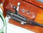
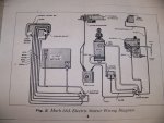
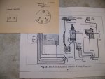
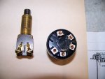
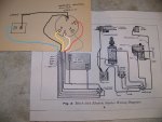
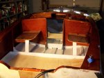
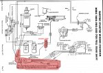
I have a Mercury Mark 58ae with the quicksilver two lever controls as pictured below with the ignition switch long gone.It broke in the early 80`s before the internet and I couldn`t find a replacement so I mounted a on off start switch in the dash.It never worked right, it wouldn`t kill the motor when switched off. I want to try again but need some knowledgeable help.Below is a print of the original wiring diagram and a drawing of the mercury 54211 switch and choke button.Thank you for any and all help.
 

Attachments

  • photo309596.jpg
    photo309596.jpg
    1.5 MB · Views: 5
  • photo309597.jpg
    photo309597.jpg
    979.6 KB · Views: 9
  • photo309598.jpg
    photo309598.jpg
    934.3 KB · Views: 7
  • photo309599.jpg
    photo309599.jpg
    709.5 KB · Views: 6

racerone

Supreme Mariner
Joined
Dec 28, 2013
Messages
38,074
The white wire going to the magneto is grounded to STOP the motor.-----Note----12 volts is not used to generate spark on this motor.-----The magneto provides spark all by itself.
 

JPO 1949

Petty Officer 3rd Class
Joined
Mar 23, 2019
Messages
96
Thank you racerone. Was hoping someone could tell me which wire to hock to which terminal. I know the blue goes to one of the terminals on the choke switch, The ignition switch is not the original , I have no idea where the other wires go.
 
Last edited:

racerone

Supreme Mariner
Joined
Dec 28, 2013
Messages
38,074
I have a few of these 4 cylinder " cloud white " 40 / 50 HP motors.----I am not very adept at giving wiring instructions.----The wiring diagram should help you.
 

JPO 1949

Petty Officer 3rd Class
Joined
Mar 23, 2019
Messages
96
Haven`t sleep in two days trying to figure this out. This is what I`m going with. I`ll let you know how it works out when I try to start it up. Thank you.
 

Attachments

  • photo309627.jpg
    photo309627.jpg
    1.1 MB · Views: 6
  • photo309628.jpg
    photo309628.jpg
    888.4 KB · Views: 2

Willyclay

Captain
Joined
Sep 8, 2006
Messages
3,260
If you have not already done so, I recommend you use a multi-meter to "map" every terminal combination on the replacement ignition switch for continuity in each switch position; i.e. Off, On, Choke, Start, Run. That should help you determine what is going on inside your switch and, hopefully, avoid sending 12V to the wrong place. Good luck with that great old motor!
 

JPO 1949

Petty Officer 3rd Class
Joined
Mar 23, 2019
Messages
96
Thank you Willyclay, took your advice and mapped the terminals for continuity , this is what I came up with.

OFF- E white wire-magneto
D black wire ground

ON- A green wire battery positive
F red wire rectifier

Start- B yellow wire starter silenoid
A green wire battery positive
F red wire rectifier

If I wire it this way am I going to fry anything. How can I find out what should happen in each position ?
 

Willyclay

Captain
Joined
Sep 8, 2006
Messages
3,260
It's been a very long time since I had my hands on one of these old beauties and it was a Mark75E. You can see my signature clearly states I am not and never have been trained on anything. Strictly hands-on experience and making mistakes. That said, I hate electrical issues because one corroded connection can completely shut you down, BTDT.

Your map looks correct to me when I follow the wiring diagram but I do have one question. You stated the motor would not shut down in the OFF position and Racerone identified the White wire is used to ground the magneto which kills it. Looks to me like there should be a Ground wire from the stud on the magneto to the powerhead AND it appears to have a "mercury switch" in-line to the grounding point. I think that wire/connection needs to be examined carefully for proper functionality of the "mercury switch" and/or corrosion on the stud, terminals, grounding lug on the powerhead and the wires themselves.

I will not tell you how many hours I searched for a similar problem ultimately to determine one wire was corroded internally; under the insulation. It would pass continuity tests BUT would not allow enough voltage to flow. I read your thread in the Restoration Forum where this boat/motor was used in saltwater early in its life. It's usually the simple stuff, good luck!
 
Last edited:

JPO 1949

Petty Officer 3rd Class
Joined
Mar 23, 2019
Messages
96
Willyclay, I know now why the motor wouldn`t shut down, I used the wrong switch, but I didn`t know then. I would tilt the motor and the mercury switch would shut it down, I know dumb! I feel better about wiring the switch now and trying it out but that`s going to be awhile.
 

Willyclay

Captain
Joined
Sep 8, 2006
Messages
3,260
JPO 1949, Glad to hear you are comfortable with the current switch. I will try to contribute what I can but it is getting more and more difficult to pull something out of the empty space between my 74 year-old ears. Let us know after you test it again.
 

merc850

Commander
Joined
Jul 7, 2010
Messages
2,046
Make sure the rectifier lead is always connected to + while the motor is running and don't shut the motor off at above idle speed or you can damage the rectifier.
 

merc850

Commander
Joined
Jul 7, 2010
Messages
2,046
If you want to eliminate the rectifier to the key switch upgrade it to a diode type and you can wire it to the + terminal on the starter solenoid.
diodewiringsmall.jpg
 

JPO 1949

Petty Officer 3rd Class
Joined
Mar 23, 2019
Messages
96
merc850, is this something I can do if my rectifier goes out ? Most of the electrical parts as well as many other parts for this motor are obsolete now. What are the benefits of a diode type rectifier other than availability ? If my battery goes dead I can disconnect the red lead at the rectifier and pull start it. I`m guessing it would be the same with the diode type rectifier.
 

merc850

Commander
Joined
Jul 7, 2010
Messages
2,046
The original rectifiers were selenium plates that can build up corrosion resistance over time, the diode type is more robust and you can get one from Mercury or elsewhere. You can also get a rectifier/regulator type if you are going to use a sealed marine battery and to protect your electronics. Don't disconnect the red wire from the battery or this will damage the rectifier and you don't need to do it anyway, you can leave the old rectifier in place - disconnected and hide the new rectifier somewhere to preserve the old look.
 

JPO 1949

Petty Officer 3rd Class
Joined
Mar 23, 2019
Messages
96
Thank you merc850, that is really good information to know. I may look to upgrade in the near future. If you were going to upgrade to a diode type rectifier what would you use. My boat is a simple little runabout with no electronics other than a portable gps. It has a magneto if that makes a difference.Not worried about the looks other than neat. I`m more of a street rodder.
 
Top