Alex@Van's
Cadet
- Joined
- Nov 5, 2024
- Messages
- 7
Hello,
I am a DC electrical parts man. We're helping a local guy get his 1954 Evinrude 25 (#25014 I believe) going. We are observing strange behavior and this forum seems to be the best place on earth to research it. I have searched the forum and did not come across this specific problem, though some threads are in the ballpark. It has stumped a seasoned small engine mechanic.
Replaced magneto cam, cam retainer, points, condensers, wires, coils, primary coil and plugs. The original cam was cracked, the retainer was broken, and the points were trashed.
If we install the lower plug, we lose spark on both cylinders. If we remove the lower plug, we get good spark up top (installed) and a spark that will jump a 1/2" gap from the lower plug.
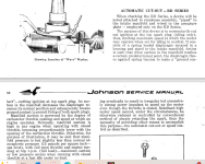
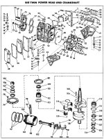
Now here's the weirdness: if we block the lower plug hole with a finger and a little compression builds in the lower cylinder, we lose spark top and bottom. Mechanic's theory is that somehow the compression is mechanically shifting something and it is grounding or losing ground. Thinking about how this engine is assembled, I can't put my finger on any suspects. Could the crank be tilting the flywheel and moving the flywheel out of gap spec or even physically grounding to the stator?
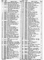
If so, I can tell you that the parts manual for the #25014 is elusive. The mag parts were largely or all the same in the #15012-15013's but the cam bearings could be different. Part number help here would be greatly appreciated.
I am not sure if there is a "runaway" vacuum switch in this early generation. There is one diaphragm switch that doesn't change anything if it is disconnected or bypassed. The wiring is quite simple.
He has thoroughly tested everything electrically including swapping around coils, ohm measurements of all 3 coils, voltage and continuity, inspection of points for defects, and basically anything we could find in forums and videos. The no-spark does not switch to the upper cylinder after swapping any part. The only common factor is the flywheel/stator. Definitely seems to be mechanical.
I can get more info or field questions, and I have linked this thread to the mechanic, who will either send me updates/addenda to post, or create an account and post himself.
To the esteemed community, I ask: HELP?
Thanks in advance.
Last edited:


