Correct Dual Battery Switch setup

sam am I

Commander
Joined
Jun 26, 2013
Messages
2,169
I’d never be able to reach my multimeter from gauge to battery. ANy ideas?

Use a spool of cheepy wire (lamp cord if need be) to extend either meter lead. Input impedance of meter is 1M ohm, 400' of 30 gauge wire will work fine with no effect on accuracy....But, cut to length just for brevity.
 
Last edited:

foilled

Petty Officer 2nd Class
Joined
Jul 10, 2018
Messages
196
Use a spool of cheepy wire (lamp cord if need be) to extend either meter lead. Input impedance of meter is 1M ohm, 400' of 30 gauge wire will work fine with no effect of accuracy....But cut to length for brevity.

Positive to positive read 12-1.5 volts. Negative to negative read .03 volts.
 

sam am I

Commander
Joined
Jun 26, 2013
Messages
2,169
1.2-1.5 key on.

That's your side, start hunting....Should come down to around .03V like the neg is when you find your issue. Also, add that drop (1.2-1.5) to all your past meter readings........Make sense now?
 

foilled

Petty Officer 2nd Class
Joined
Jul 10, 2018
Messages
196
Do I have a ground on a positive wire or a bad connection and I find that with choppy resistance?
 

sam am I

Commander
Joined
Jun 26, 2013
Messages
2,169
Battery post forward to the meter.........Look for loose connections, corrosion in connection, flaky burn't looking wires/connections, burn't/hot looking connection/s AND gold!!! But, I claim the gold if you find any.
 

foilled

Petty Officer 2nd Class
Joined
Jul 10, 2018
Messages
196
No!


Yes!


Fix it!!

You're on your own now, fly fly!!

Will do am I looking between engine or accessories or the whole boat. Also what is this issue called and what problems has my boat been subjected to running like this?
 

foilled

Petty Officer 2nd Class
Joined
Jul 10, 2018
Messages
196
Battery post forward to the meter.........Look for loose connections, corrosion in connection, flaky burn't looking wires/connections, burn't/hot looking connection/s AND gold!!! But, I claim the gold if you find any.

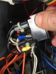
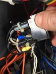
Check this photo. What do you thinks up with the burnt wire. This is to the nav switch which still works. Nav lights work but it appears switch can be turned 2 ways but only 1 way turns on all lights, switch in position 2 does nothing and off position turns it off. Thing is I’ve never seen a wire like that. It looks like no wire in it just a transparent insulation with a small battery looking piece in jt. ( you can see a non burnt one in photo right next to burnt wire on the bottom side of photo)
 

Attachments

  • A24D3F91-59F0-4356-BED1-DE02E870F6B0.jpeg
    A24D3F91-59F0-4356-BED1-DE02E870F6B0.jpeg
    1.4 MB · Views: 1
  • A24D3F91-59F0-4356-BED1-DE02E870F6B0.jpeg
    A24D3F91-59F0-4356-BED1-DE02E870F6B0.jpeg
    1.4 MB · Views: 1

alldodge

Moderator
Staff member
Joined
Mar 8, 2009
Messages
40,804
The Nav switch in one way should turn ON red/green and anchor light. In the other position should only turn ON the anchor light.

Nav for driving
Anchor for anchor
 

foilled

Petty Officer 2nd Class
Joined
Jul 10, 2018
Messages
196
The Nav switch in one way should turn ON red/green and anchor light. In the other position should only turn ON the anchor light.

Nav for driving
Anchor for anchor

Is that a special type of wiring where it’s burnt out? Why couldve burnt out so I can replace
 

alldodge

Moderator
Staff member
Joined
Mar 8, 2009
Messages
40,804
I don't think so, could be it burnt so previous owner cut it off and rewired
 

foilled

Petty Officer 2nd Class
Joined
Jul 10, 2018
Messages
196
I don't think so, could be it burnt so previous owner cut it off and rewired

The other burnt end is isn’t connected either. Leaving a completely blank terminal on back of switch. I have 14 gauge wire but I just checked it out the wire isn’t regular wire it’s a hard metal on there that isn’t normal wire
 

Silvertip

Supreme Mariner
Joined
Sep 22, 2003
Messages
28,764
The nav/anc switch requires a diode which is what you are looking at. In one position both the bow and stern lights should be on and the diode is not required. In the ANC position only the stern light must be on. Using the switch in the picture requires the diode which blocks current going to the bow light when the switch is in the ANC position. It either broke off, or due to vibration partially broke off and the reduced wire size couldn't handle the current and it fried. But that's not likely the cause of your other problem(s).
 

foilled

Petty Officer 2nd Class
Joined
Jul 10, 2018
Messages
196
The nav/anc switch requires a diode which is what you are looking at. In one position both the bow and stern lights should be on and the diode is not required. In the ANC position only the stern light must be on. Using the switch in the picture requires the diode which blocks current going to the bow light when the switch is in the ANC position. It either broke off, or due to vibration partially broke off and the reduced wire size couldn't handle the current and it fried. But that's not likely the cause of your other problem(s).

Thanks. Is there another way to help pinpoint voltage drop. I’m still having trouble finding it?
 

alldodge

Moderator
Staff member
Joined
Mar 8, 2009
Messages
40,804
I started reading thru the thread again and for the most part I think your chasing a ghost. While there is some voltage drop, this can be many things and in most cases its from corrosion. This slight drop is also IMO not going to make much of a difference if found.

Running on both will charge both bats, and agree one will have a different charge then the other. Same thing happens when using an ACR, but the ACR will make sure the start bat is protected if the other bat has an issue.

Charge both bats seperately and then take off the charger and let sit for a couple hours. If the bats are at least 12.5V (90% charge) then go boating. If they are below this value look at replacing
 

sam am I

Commander
Joined
Jun 26, 2013
Messages
2,169
Is there another way to help pinpoint voltage drop. I’m still having trouble finding it?

In order to find the drop and given its consistently there and is around 1.2-1.5V volts with varying loads

A few other ways are possible but, none simpler than walking down the path and checking nodes..........

Above, you found the drop to be on the positive side of things, therefor........

1) Find and identify the main positive voltage feed from the battery to the helm, there's ONE main path with branches (your meter is/on a branch)

2) Turn on load/s that create the repeatable drop.

3) Go back to your positive side test you did above, one meter lead (pos) to the battery + and the other meter lead (neg) to the gauge +

4) Re-verify drop is occurring..you said you can get 1.2-1.5V.

5) Leaving the meter lead (pos) alone and remaining securely connected to the battery +,

6) With the OTHER meter lead (neg) that is on gauge +, start working (probing) your way backwards towards the battery down the main feed path you identified in #1 above backwards towards the battery probing points of interests (connection, junctions., slices and what have yous)

Example A

You probe (pierce the insulation with a needle) of the wire 2" down from where the gauge + point, you look at you meter and it still reads that 1.5V drop........

Explanation A......

This result seems logical because it only 2" from the gauge + connection and the wire looks normal and in good shape (not been hot, frayed, spliced etc etc)


Example B

You probe (pierce the insulation with a needle) of the wire 3' down the main path from the gauge + point, you look at you meter BUT now, the drop is GONE, it reads 0.03V.

Explanation B......

This is because as you moved the meter probe (neg) further from example A's probe point towards the battery along the main feed path, you jumped over THE ****ty connection.

Now, logically you know the problem (the voltage drop) HAS to be between example A and example B. Work your way FORWARDS toward example A looking for a suspect connection, splice, hot spot.

This is most likely how a mechanic would find the problem, no real other way and I really don't think I personally could make a better explanation of this process.

If this process is confusing, hard to follow and you can't seem to use this method of logically dividing and conquering, then perhaps the mechanic would be the better choice for you to get your problem (voltage drop) resolved.
 
Last edited:
Top