eska /gamefisher 9.9/15 cdi fix replacement

Status
Not open for further replies.

truckintyler

Petty Officer 3rd Class
Joined
Jun 26, 2010
Messages
77
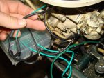
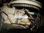
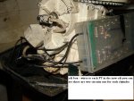
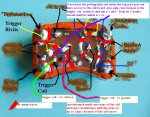
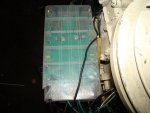
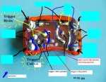
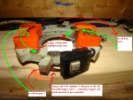
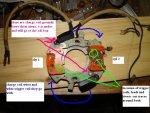
here are some pictures of what i have done, i wanted to get some of under the flywheel and show the main part but... having trouble getting flywheel off.
 

Attachments

  • cdi 5.JPG
    cdi 5.JPG
    82.9 KB · Views: 11
  • cdi 3.JPG
    cdi 3.JPG
    96.9 KB · Views: 11
  • cdi igntion.jpg
    cdi igntion.jpg
    14.7 KB · Views: 11
  • cdi 4.JPG
    cdi 4.JPG
    75 KB · Views: 10
  • cdi 1.jpg
    cdi 1.jpg
    48.2 KB · Views: 10

truckintyler

Petty Officer 3rd Class
Joined
Jun 26, 2010
Messages
77
Re: eska /gamefisher 9.9/15 cdi fix replacement

more
 

Attachments

  • cdi igntion 2.JPG
    cdi igntion 2.JPG
    98.2 KB · Views: 8
  • cdi 6.JPG
    cdi 6.JPG
    58.8 KB · Views: 8

MahtyMaht

Chief Petty Officer
Joined
Apr 7, 2010
Messages
605
Re: eska /gamefisher 9.9/15 cdi fix replacement

This is GREAT, man! Great, I say. I think even I could do that with this info. I think I'm gonna start rooting around in my electronics stuff, and see if I don't have a 10 amp scr...........
 

truckintyler

Petty Officer 3rd Class
Joined
Jun 26, 2010
Messages
77
Re: eska /gamefisher 9.9/15 cdi fix replacement

I ordered most of the electronics from digikey.com they ship really fast
 
M

mrcrabs

Guest
Re: eska /gamefisher 9.9/15 cdi fix replacement

Tyler, what size caps did you use?, I see you have them in series on your board. To bad you have to totally depot the whole back side to make all of those trace cuts...any way around that?
 

truckintyler

Petty Officer 3rd Class
Joined
Jun 26, 2010
Messages
77
Re: eska /gamefisher 9.9/15 cdi fix replacement

anyway around that?.. well they way i see it was either make new housings for the trigger coils. or keep them in place in the old modules, i mean seriously, the module is 35+ year old electronics junk. i just wanted it to work. i didn't care about keeping it original.
as for cutting the old traces i just didn't want the old resistors, diodes or scr to mess with my new circuit in anyway.
up to you , the only concern is that trigger coil which controls the advance which the uses the small magnet/spring contraption under the flywheel.
the charge coil wire(+) just runs to the new CDI box now.
oh my new caps were .47 uf 400v metal poly caps x 4 two for each circuit
did you want the whole part list?
 
M

mrcrabs

Guest
Re: eska /gamefisher 9.9/15 cdi fix replacement

i didn't care about keeping it original

I'm only interested in depotting at the moment, I made a template map for the single SSI and using a depth gage for drilling cutting and heating and popping to make depotting quicker and less messy...I don't want to breath that crap all day. And no I don't want you parts list, I was just curious about cap size you were using, I understand @ 630v 1uf it possibly 3-4 times the capasity it needs to work.
 

truckintyler

Petty Officer 3rd Class
Joined
Jun 26, 2010
Messages
77
Re: eska /gamefisher 9.9/15 cdi fix replacement

i suppose. when i tested the old cap that came out of the bad module it was fine. the scr is the problem, i'm just happy i saved the 250 bucks
i'm making a new cdi box much smaller. might get rid of the old one i made
 

MahtyMaht

Chief Petty Officer
Joined
Apr 7, 2010
Messages
605
Re: eska /gamefisher 9.9/15 cdi fix replacement

Does that SCR have to move much heat? I'm wondering if it would like some heat sink fins hangin' out of the potting material.
 

truckintyler

Petty Officer 3rd Class
Joined
Jun 26, 2010
Messages
77
Re: eska /gamefisher 9.9/15 cdi fix replacement

Does that SCR have to move much heat? I'm wondering if it would like some heat sink fins hangin' out of the potting material.

i dont think so, but wouldnt hurt anyways,
 

MahtyMaht

Chief Petty Officer
Joined
Apr 7, 2010
Messages
605
Re: eska /gamefisher 9.9/15 cdi fix replacement

Hey, Tyler - what's ohms value of the 51 watt resistor that gates the scr? I think I would like your parts list.
 

truckintyler

Petty Officer 3rd Class
Joined
Jun 26, 2010
Messages
77
Re: eska /gamefisher 9.9/15 cdi fix replacement

parts for cdi box
4 x .47uf 400v metal poly capacitor
2 x .010uf 100v ceramic capacitor
2 x 1000pf 100v ceramic capacitor
2 x 51 ohm 2w resistor metal film <---- sorry its a 51 ohm not 51 watt
2 x 1.0 k ohm 2w "" ""
4 x 1.0 M ohm 2w "" ""
2 x 1n4004 diode 400v
2 x 10uf 25v aluminum electrolytic capacitor
2 x bt151 scrs
thats enough to make the two circuits one for each cylinder.

how is yours coming along mahtymatt? i just started on a smaller one. so i could mount it better
 

MahtyMaht

Chief Petty Officer
Joined
Apr 7, 2010
Messages
605
Re: eska /gamefisher 9.9/15 cdi fix replacement

It's my poor neighbor's 9.9, and he really doesn't want to give it up, but I got it a at yard sale for $25, and gave it to him. He's been unwilling for two years to cough the $250 for a CDI replacement stator, and now he has a Johnson 6 hp, so he doesn't need it. I'm going to order these components from Mouser, fabricate the circuits, then I'll go buy or borrow the motor for field testing. He needs some time to finally just give it up, but I think he will. I'll keep ya posted, though, and thanks a million for the parts list and pics. I have seen that article before, but I had no way to tell if the induced current went positive or negative first, so I gave it up.
 

truckintyler

Petty Officer 3rd Class
Joined
Jun 26, 2010
Messages
77
Re: eska /gamefisher 9.9/15 cdi fix replacement

It's my poor neighbor's 9.9, and he really doesn't want to give it up, but I got it a at yard sale for $25, and gave it to him. He's been unwilling for two years to cough the $250 for a CDI replacement stator, and now he has a Johnson 6 hp, so he doesn't need it. I'm going to order these components from Mouser, fabricate the circuits, then I'll go buy or borrow the motor for field testing. He needs some time to finally just give it up, but I think he will. I'll keep ya posted, though, and thanks a million for the parts list and pics. I have seen that article before, but I had no way to tell if the induced current went positive or negative first, so I gave it up.
Thought the same thing about the current but when the multimeter didn't go negative I guess it was ok.
 

MahtyMaht

Chief Petty Officer
Joined
Apr 7, 2010
Messages
605
Re: eska /gamefisher 9.9/15 cdi fix replacement

I ordered the components from Mouser last night, and frankly, I'm as geeked up as a silly school girl with a brand new Easter dress. I'm thinkin' I'll put some pics up as I go, because this Tecumseh SSI thing is a recurring issue, and if I can get away with this, it will help some of these guys that come in here with the same old problem.
 

truckintyler

Petty Officer 3rd Class
Joined
Jun 26, 2010
Messages
77
Re: eska /gamefisher 9.9/15 cdi fix replacement

Also forgot two parts
6 x 1n5408 diodes
And 2x NTC 500 ohm thermistors
Sorry about forgetting those
 

MahtyMaht

Chief Petty Officer
Joined
Apr 7, 2010
Messages
605
Re: eska /gamefisher 9.9/15 cdi fix replacement

Also forgot two parts
6 x 1n5408 diodes
And 2x NTC 500 ohm thermistors
Sorry about forgetting those

Thermistors? I don't recall seeing thermistors in there? What do they do? I would expect to be able to get the diodes at the Radio Trash.
 

truckintyler

Petty Officer 3rd Class
Joined
Jun 26, 2010
Messages
77
Re: eska /gamefisher 9.9/15 cdi fix replacement

Thermistors? I don't recall seeing thermistors in there? What do they do? I would expect to be able to get the diodes at the Radio Trash.
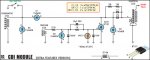
"A second improvement involves the use of a negative temperature coefficient (NTC) thermistor across the gate of the SCR. This thermistor reduces its resistance with increasing temperature and is used to compensate for the lowered triggering requirement of the SCR (for both voltage and current) at higher temperatures.

Effectively, the NTC thermistor forms a voltage divider with the 51W resistor. At 25?C, the thermistor is 500W and so it attenuates the signal from the trigger coil to 91%. However, at 100?C, the NTC thermistor resistance is around 35W and the trigger signal is divided down to 41% of the trigger coil value.

This attenuation in signal level attempts to match the SCR?s reduced trigger level requirement at higher temperature. So as temperature rises, the signal is increasingly attenuated and as a consequence, the SCR fires at the same trigger coil voltage over a wide temperature range. Without the thermistor, the SCR would be subject to timing changes with temperature."

not sure if it helps much but i put in in anyways, ummmm you could leave it out.
mine runs with it.
 

truckintyler

Petty Officer 3rd Class
Joined
Jun 26, 2010
Messages
77
Re: eska /gamefisher 9.9/15 cdi fix replacement

here are some more pics to help.
 

Attachments

  • cdi step zero.JPG
    cdi step zero.JPG
    61.1 KB · Views: 7
  • cdi step two.JPG
    cdi step two.JPG
    94.8 KB · Views: 7
  • cdi step one.JPG
    cdi step one.JPG
    81.3 KB · Views: 7

MahtyMaht

Chief Petty Officer
Joined
Apr 7, 2010
Messages
605
Re: eska /gamefisher 9.9/15 cdi fix replacement

I gotta look at that article again, 'cause I completely missed that, and it sounds worth doing. Great pics, by the way.
 
Status
Not open for further replies.
Top