My Rotten Lady

kramerpage

Chief Petty Officer
Joined
Jul 26, 2010
Messages
447
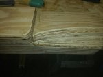
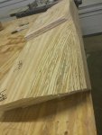
kramerpage, I over killed my engine mount also and overkill is not a bad word when it comes to rebuilding these boats. I made my motor mount out of 1/2 & 3/4 plywood glued and screwed together making one big piece of plywood about 38" wide, 10" tall in the middle and 10" front to rear. Go with what Wood said that is how mine was put in then tabbed it with several over lapping layers of 1708.

I have to go with what he says. I have no idea what the heck I'm doing. Lol. I had a gallon of titebond 3 thinking I would never use that much glue. We'll I need more glue. My brothers asking where did you put the glue I cut my seat boxes. I said sorry guy it's gone.
I'm not screwing mine but using two pnuematic nail guns last level was 3 1/2 inch nails. Rows and rows of nails. Sure takes alot longer when you have to laminate two ply to make an inch rather than have an I inch ply on hand. Of corse I couldn't find inch ply. These mounts are 3 times the weight as the old. Thanks
 

kramerpage

Chief Petty Officer
Joined
Jul 26, 2010
Messages
447
Summer in Seattle my friend. It only lasts for 2.5 days :)

WoG got you covered. I am not clear on the orientation of this engine mount regarding how it is going to be laid down in the hull. Can you post a picture of a dry fit?

DP waz up?

I know I needed to dry fit and get a pic but I just ran short of time. I see my pic skills are sub part making it difficult to understand. The last pic is the mount upside down showing the rise of the hull. The mounts are 41 inches long and run with along side of the 3/4 inch stringer. They are 9 inches wide.

As stated a couple post ago I need to decide if I should make them taller to get rid of the chalks that were under each metal motor mount. The tops of the 41 inch long mounts have a onich ply pad that is 14 x 9. This is where the motor mount physically rests. I could cut another pad or two thus eliminating the chalks. Now is the time. Can you look at those pics and share your thought? Thank you
 

DeepBlue2010

Lieutenant
Joined
Aug 19, 2010
Messages
1,304
That is what I thought. Honestly, these steps with their sharp edges resting on the hull concern me more than the chalks. chalks are fine to achieve the final height for the engine mount. They also reserve the flexibility to change the height (in case of a repower) without tearing apart the whole mount. But these steps are kinda of new to me. I would have made a rectangle out of plywood cuts and cut them to an angle to match my hull on a table saw so that at the end, the mount blanks are vertical with one blank on top that is horizontal. Something like this (Sorry for the crude drawing but you get the idea)
mount.gif or thismount2.gif


But this is just me and how I would do it, sure different people will have different opinions.
 
Last edited:

kramerpage

Chief Petty Officer
Joined
Jul 26, 2010
Messages
447
Oh I see DB. I was trying to recreate the method Woodonglass described to me in an earlier post where he made a drawing for me.
The original mount had only one outside 1 inch peices cut at a 90 not to the degree of the hull. It was not bedded in anything. Just glassed to hull. I can't change it now there is tons of glue and nails. If I sanded the edges it would disturb all the elevations that I created to exactly duplicate.

I asked the question Friday to make sure I was doing it right. Come Saturday I had to get off the pot. I had three people working on different aspects. An electrician upgrading wire sets and die crimping all the large dual battery and starter conductors, and two people doing gel coat exterior restoration.

Thanks for taking the time to draw out your method. I appreciate all your input and wisdom here.
 
Last edited:

Woodonglass

Supreme Mariner
Joined
Dec 29, 2009
Messages
25,924
Don't think there should be any sharp edges on the hull if they're installed properly. Everything should be embedded in the tiger hair just like a stringer so no wood is touching the hull.;)
 

DeepBlue2010

Lieutenant
Joined
Aug 19, 2010
Messages
1,304
I am afraid the laws of physics, specially gravity, would disagree. Those sharp edges will sink in any bedding compound hairy or not. The only way they will not is to hold the platform suspended above them until they cure as we do with the stringers. This is an engine mount however, if held suspended this means the whole platform has clearance to give under the engine weight jumping a wake while under way or cruising through a choppy waters which can screw alignment and cause costly repairs.


From an engineering stand point, this structure needs to have flat bottom. Moreover, it would be way more sound - structurally - if it is build with either solid wood or vertical cuts of plywood.

And by the way, if it was made with completely flat base, bedding is not even necessary. The surface area is wide of the mount base is wide enough to the point that hard spots are not even a concern.
 
Last edited:

kramerpage

Chief Petty Officer
Joined
Jul 26, 2010
Messages
447
Geee Whizzz guys. What if I used this Arjay megium weight bonding compound? I could fare in the gaps between the corners on the mount before I bed the mount in the boat. I have 2 gallons on hand. I spoke to the GM a month ago and he recommended it for any structural bedding specifically wood mounts as long as they were poly coated before hand. I have used this compound on my brothers Baha resto and we had good results with it. It's the consistency of auto Bondo compound. It does have fiberglass hairs in it. You activate it with the supplied harder. It trowels out nice and is easy to work with. Working rime is 20 minutes tops. It's sands like bondo. Here's a link to the pdu tech sheet. It's called Arjay 2011 bonding compound. Thanks

http://www.arjaytech.com/index.php/our-products/medium-weight/2011
 

DeepBlue2010

Lieutenant
Joined
Aug 19, 2010
Messages
1,304
Honestly, I don't believe this structure to be suitable for its function but it is your call.
 

kramerpage

Chief Petty Officer
Joined
Jul 26, 2010
Messages
447
Honestly, I don't believe this structure to be suitable for its function but it is your call.


Hi DB!!!

I believe that the current design far exceeds the original design which served the boat well for 510 hours on the rough seas of Lake Erie. The factory design was 2 inches of horizontal plywood with one drop support on the inward edge and filled with foam.

I understand an I beam erected vertically, both being of same size, is much stronger than one erected horizontally. Simple engineering. So there is no doubt that vertical ply would be a much much stronger load bearing structure. Understood.

Also I understand, that loading thru the solid horizontal plywood verses loading thru 2 inches of two part foam will be much more load bearing and be able to disperse energy more efficiently.

The great thing about this forum is that we can share our experience and knowledge.

I will continue the mount construction as pictured and will bed them in bubble gum not tiger hair. (Arjay 2011 bonding compound) I spoke with the manufacture today in tech support and he echoed what the distributor stated which was this is the perfect application for this product. It will be like a "tank".
He also stated there is no need for filets of PB.

1) Apply compound to mount location via trowel to a half inch depth
2) Set structure in compound
3) "Set" and level structure by striking with leather mallet to desired elevation
4) Tool excess compound
5) Allow cure time
6) Apply glass cloth

Again thanks for all the ideas and time spent helping others on this forum. Its awesome and fun. I'm having fun, are you?
 

DeepBlue2010

Lieutenant
Joined
Aug 19, 2010
Messages
1,304
I sure do! Debating design ideas and poking holes in architectures and trying to find every possible way they will not work is what I do for living. We do this not because we want give each other hard time but rather to achieve the best and most reliable design possible. After all, that is what we are getting paid for. None of this should be taken personally. And as I said before

" this is just me and how I would do it, sure different people will have different opinions."

Also, as I said before, it is your boat and your call. Build it whichever way you like.

I wish you best of luck with your build
 
Last edited:

Mark72233

Ensign
Joined
Jul 11, 2014
Messages
926
kramerpage, here are pictures of my old and new motor mount. This is for twin Merc 165hp I/Os. Under the fiberglass it was just pieces of 4x4 shaped to the curve of the hull.


Here is the new motor mount upside down. The small piece of PVC pipe was to shape the PB for the pipe that I ran the length of the bilge from the front of the boat to the back.

Here it is PB to the hull.

Here it is covered in 1708 and painted.
 

kramerpage

Chief Petty Officer
Joined
Jul 26, 2010
Messages
447
Nice Mark. That's how I'm gonna finish mine. White. I'm using 4 layers of 1708 on mounts and 1.5 CS on all other surfaces then two coat of white gel coat. I'm only doing a partial on mine not the whole boat. That's awesome guy.
 

kramerpage

Chief Petty Officer
Joined
Jul 26, 2010
Messages
447
Well I sanded for 1 1/2 hours last night continuous. Filled a five gallon shop vac. Can you save that glass powder and sell it on ebay? My ppe carries plugged up and the face mask kept fogging so I had to call it quits. Those carriages are like 39.00 cause I got vapors gas type not just particulate. So in 3.5 total hrs of use they were done. Better them than my lungs. Worked on my brothers boat for 4 hours constructing seat boxes. I did get to use poly resin and cloth for the first time. Cloth on the interior 90 degree joints and total encapsulated box in resin w wax. He called me today excited and said they came out looking great and rock hard. So I was happy I could help him with stuff I learned from you guys. Thanks.
 

kramerpage

Chief Petty Officer
Joined
Jul 26, 2010
Messages
447
What is the method of cloth application when applying 1.5 cs to a deck hatch compartment? Like a storage box below deck between stringers.
Run cloth upside first them place bottom square in last? Ant experiences? Thank you 20140709_203947.jpg
 

kramerpage

Chief Petty Officer
Joined
Jul 26, 2010
Messages
447
No Title

Got the motor mount wood completed today. There were some difficult compound cuts that had to be made that make room for the starter and other mechanicals. Getting prepared to remove the rotten stringer on port side so I can make a new one in the shop. Then I have a cross piece that ties the mounts together that sits aft of the bulkhead that also needs replaced. Drilled a few more holes in the transom at the very bottom sine I can now get to the last six inches and it was fine thank god. Trying to put in 2 full days in this weekend.
 

Attachments

  • photo228202.jpg
    photo228202.jpg
    91.8 KB · Views: 0
  • photo228203.jpg
    photo228203.jpg
    113.7 KB · Views: 0

kramerpage

Chief Petty Officer
Joined
Jul 26, 2010
Messages
447
It's crazy lifting these in and out. My brothers Baha has the big HP go fast motor and his mounts are an upside down U like 2x4 size. Very small. He laughs at the overbuild on mine.

So do I need to replace foam in the two cavities I'm demoing?? I would like to not. They r small like 14x14 and 14x20. Probly 3 inch foam at deepest point to 1/4 inch at top of dead rise. Thanks
 

kramerpage

Chief Petty Officer
Joined
Jul 26, 2010
Messages
447
Well the rot was more than I thought. I had to cut the stringer about 43 inches from transom. This is at the engine bulkhead area. I cannot get behind the stringer to sister the joint as planned due to there is no access under the fiberglass floor. So now how do I make the repair?
 

kramerpage

Chief Petty Officer
Joined
Jul 26, 2010
Messages
447
No Title

Filled the transom are holes today and gel coated the key hole. I made the Mikey Ears angle more severe as I could see where the steering atm was hitting. Poly ed the first coat of gel. PB went well. Waiting to solve the sister stringer issue above so I putter ed around and cleaned up the shop.
 

Attachments

  • photo228338.jpg
    photo228338.jpg
    117.4 KB · Views: 0
  • photo228339.jpg
    photo228339.jpg
    125.3 KB · Views: 0
  • photo228340.jpg
    photo228340.jpg
    61 KB · Views: 0
  • photo228341.jpg
    photo228341.jpg
    96.7 KB · Views: 0
Top