*ding*...You've got oil

bruceb58

Supreme Mariner
Joined
Mar 5, 2006
Messages
30,478
Yep, engine is too high. You are adjusting the front of the engine so high in front makes the coupler lower in rear. Engine is pivoting on the rear transom mount points.

Rotate the engine 180 and see if it is still a problem just to make sure you don't have a coupler issue.

I rotate my engine in 90 increments when I get close to my final adjustments to make sure the tool slides in equally in all positions.
 
Last edited:

pantaloonz

Petty Officer 1st Class
Joined
Nov 28, 2014
Messages
237
oh!!!! DUH!!

The front of the engine is not near the transom.. silly me.

Ok newbie now.. I keep hearing rotate engine 90 degrees... I'm sorry but I don't know how to do this...I assume you mean rotate the coupler, but Im no familiar with this term or process
 

bruceb58

Supreme Mariner
Joined
Mar 5, 2006
Messages
30,478
Either bump the starter or rotate the engine with a socket on the crank bolt. Doesn't have to be exact.
 

pantaloonz

Petty Officer 1st Class
Joined
Nov 28, 2014
Messages
237
ahh ok... I was hoping you'd say that..
gotta put it to bed tonight another chance of lightning and such

Should I start to consider that it's hitting to the right as well and not right at the top of the coupler? There is no side to side mount.. maybe that's why my old gimbal was "tweaked" in that direction, well in any event on to the motor mounts,. at least THAT is a straight forward simple tool adjustment..

may take many tries but I know what I'm after now..

Getting closer....

-Pantz
 

skippy2235

Petty Officer 2nd Class
Joined
Aug 24, 2009
Messages
138
See glad you got the tool now. :)
we have learned the hard way. Like you. Now you can tell folks, what you learned.
Thanks for putting up with us.
I am still here, these other guys are right on target so I have nothing to say.
 

bruceb58

Supreme Mariner
Joined
Mar 5, 2006
Messages
30,478
The only adjustment is up and down. That is why I suggested you rotate the engine.

The adjustments will be very small. 1/4 turn at a time. Do each motor mount the same.
 
Last edited:

pantaloonz

Petty Officer 1st Class
Joined
Nov 28, 2014
Messages
237
Thanks Bruce,

Got it! -- Read the service manual in regards to the procedure, it's pretty basic stuff in the manual. Read through a few other links in regards to this procedure. It rained again last night so I didn't try to get to the mounts. The flooring/decking around the engine will be a little bit tight but I know exactly where the mounts are now and I'll probably strart working this through next week evenings. (got a camp invite this weekend)

I have to say again, thank you to specifically you and OffD on this one, it's pretty clear I was running the out drive under less than optimal conditions. Rotating the engine shouldn't change the impact point of the alignment tool, if it does (the impact point moves with the coupler) however, it would indicate the coupler is failing, right?

A bad coupler is not something I'm prepared to handle as I'll have to get the engine out.. :( that would make me a sad panda.

Anyone got a cost estimate to replace a coupler just so I'm prepared for sticker shock.

-Pantz
(I'm probably even further along than you expected now eh? .. ) --
 

skippy2235

Petty Officer 2nd Class
Joined
Aug 24, 2009
Messages
138
Price for Couplers are about $300 ebay, Only brand on market is
On Sale $337.11 Sierra Marine Engine Coupler 18-21753 is equivalent to parts:

Fits: 5.0L & 5.8L ( 1989 - 96)
 
Last edited:

Offrddrver

Petty Officer 3rd Class
Joined
Sep 19, 2009
Messages
95
No Title

Pantz,

I ran into the nearly the same hit point that you are drawing up in your picture. 1 o'clock hit point.
Keep in mind that my out drive was so far out of alignment I couldn't get the out drive off without using my hydraulics to push it off. (when I bought the boat)

After two attempts, the second using the correct alignment bar, I was able to get it aligned.

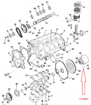
My overall point here is that even with a horrible alignment when I bought the boat, and a not great alignment after my first learning lesson, my coupling mount is still in tact 14 years later. So hopefully you won't need the pics here, but I thought I would add them so you see what you are working with, and why you do want a good alignment so you don't damage the coupling mount. Over $350.00 plus hardware costs of around $100.00.

Just take your time and small moves like Bruce noted.
For what its worth I'll measure mine and post it for you, but probably a very long shot it'll be close. But it might give you a starting point.

On my second alignment I started by measuring the front mount height (left and right) and made them equal. Then I made equal 1/4 turns of the mounting nuts to lower the motor in the front. Then I worked on shifting away from the 1 o'clock hit point by moving only one of the front mounts slightly. Once I had equal grease spline marks, and the bar slid in/out with ease then I rotated the motor with a socket and driver on the crank shaft bolt from 12:00 (start) to 3:00 to 6:00 to 9:00 and back to 12:00. Checking the alignment at each point.
(If it helps, put some mark on the crank shaft pulley to mark your start 12:00, 3, 6, and 9 o'clock points)

Just go slow and note mentally or on paper the moves you see when making adjustments.

Offrddrver
 

Attachments

  • photo228096.PNG
    photo228096.PNG
    227 KB · Views: 0
  • photo228097.PNG
    photo228097.PNG
    106.9 KB · Views: 0
Last edited:

pantaloonz

Petty Officer 1st Class
Joined
Nov 28, 2014
Messages
237
OffD,

Get out of my head man.. that's just about identical to what I've jotted down on a piece of crib notes here: hahahahaha awesome!


1. check mounts and get them on plane with each other.
2. check tool
3. get the tool so it goes in vertical first
4. turn motor??? (questioning myself)
5. adjust 1 mount if i have a horizontal issue
6. rotate motor and do the grease spline tests.

Thank you Skippy for the parts info!

-Pantz
 

Offrddrver

Petty Officer 3rd Class
Joined
Sep 19, 2009
Messages
95
Pantz,

Trying to model this with some office parts. Make it 3D. (using a paper clip holder, a Dry Marker and post it notes......funny)

1 o'clock indicates a high front and even higher front right (as looking from the back of the boat forward)

Measure front right and lower it to match the front left.
Hopefully this moves the bar more to the 12:00 position.
Then start lowering them equally to get centered.

Offrddrver
 

bruceb58

Supreme Mariner
Joined
Mar 5, 2006
Messages
30,478
Quit worrying about the horizontal issue for the moment. If you have a horizontal issue, the mounts at the transom have a problem. You CAN NOT correct a horizontal problem with the front mounts. Don't adjust one mount!

The reason you hit sideways is likely because your gimbal bearing is cocked slightly but that will get aligned by itself as you continue.

When you get the alignment bar in and slightly inserted, use a rubber mallet and tap up down and right left on the bar. That will help getting the gimbal bearing swivel carrier somewhat aligned.
 
Last edited:

pantaloonz

Petty Officer 1st Class
Joined
Nov 28, 2014
Messages
237
Sounds good guys thanks!

no more posts for me until I actually start the work on this middle of next week.

-Pantz
 

pantaloonz

Petty Officer 1st Class
Joined
Nov 28, 2014
Messages
237
Ok long time coming update. ; Got the boat in the garage and set about some work

I'll skip all the in betweens and get right to it.

I adjusted the front motor mounts on both sides all the way down to the Jam nut on both mounts (I was cursing the guys who build the flooring in this thing)

The results!!.......???

NOTHING! Nada, Zilch, Zero.. and a thrown wrench. (I did find it)

But seriously the front motor mounts cannot go lower, the alignment tool is bumping the coupler in the EXACT same place. Top at the 1 position oclock looking inside the pivot housing from the rear The alignment tool will not even begin to pass into the splines.

I do have a new gimbal bearing, does it need to "set": *insert whacking sounds"

I keep reading about this "setting" of the bearing. I thought This cannot be done until the alignment tool goes at least a 1/2 inch or past the beginning of spline/coupler correct? The whole point of the "thumping" the end of the alignment bar is to put the bearing in proper positioning for fine tuning the alignment?
I have not attempted this as the alignment tool will not even begin to enter the splines...?

Pretty aggravated again ;)


-Pantz
 

bruceb58

Supreme Mariner
Joined
Mar 5, 2006
Messages
30,478
Sounds like you haven't set the angle of the gimbal bearing yet. It is aimed too high. You do need to get the tool started into the coupler in order to tell whether it is too high or too low.
 

pantaloonz

Petty Officer 1st Class
Joined
Nov 28, 2014
Messages
237
Thanks Bruce

I guess that's a newbie mistake. It seems a bit rudimentary to bump the tool just to get it in the coupler. Is that normal?

Knowing that I'm high / right do I just focus on bumping the tool from the lower left to get the bearing 'set', or should I just bump from the bottom so I can get an initial insert?

After its in 1/2" bump it around from each angle to ensure a good set?

I measured the starting points of the front mounts, should I reset those back before the 'set' attempt.

-pantz
 

bruceb58

Supreme Mariner
Joined
Mar 5, 2006
Messages
30,478
Everything you described sounds like a good thing to do.

This does explain why you were to the right as well. That should never happen.
 

pantaloonz

Petty Officer 1st Class
Joined
Nov 28, 2014
Messages
237
Now I'm just wonderously amused.

I've gone from 2cm to 4.5+ cm on the engine mounts top to bottom. The alignment tool hits the coupler in the exact spot.. everytime

I did get a 1" dowel from the local hardware store, and much to my futher amusement with that I could CLEARLY see changes in the spacing around the dowel and gimbal bearing. As I'm leaving it tonight it's on the 4.5 cm space on the front mounts and cannot go much higher. The dowel is in at an obvious decline and the spacing on the top of the gimbal is far greater than the bottom of the gimbal.

When I started I had the mounts all the way down as far as they'd go and the dowel was exaclty the opposite, big gap on top little gap on bottom.

The dowel does not slide in and out gracefully but does show the spline marks quite nicely

Despite a bit of coaxing and some moderately hard thumps to the alignment bar my situation is not changed.

New Seal, New Gimbal, Alignment tool will not insert into the coupler.

I'm afraid of bumping the alignement too hard and damaging the gimbal bearing.

Based on all this info and testing there is a small matter of possibilities.

1. The gimbal did not seat properly: Highly Unlikely: I can see the age mark from the previous gimbal very clearlly and the new gimbal is on the outline, 360 degrees.


2. The inner part of the gimbal is angled upward: In my eyes this is the ONLY possible answer. But it doesn't make me feel good in anyway.. it was a brandnew gimbal and I didn't mess with it.. just stuck it in the freezer, then stuck it in the housing. Never touched a thing..

Suggestions are definitely welcome.

-Pantz
 

pantaloonz

Petty Officer 1st Class
Joined
Nov 28, 2014
Messages
237
by looking around and reading some more.. I guess I'm being too gentle on the gimbal.

I guess my next best bet would be to use my dowel and get it back as close to good "eyeballing" --

The be a bit more aggressive with the alignment bar. I know I'm hitting top right from about 11 to 2 oclock so I get a fairly hefty bump from the lower left of the alignment tool is in order.

Is it better to actaully bump the tool or just apply even pressure in the direction you need to go?

-Pantz
 

bruceb58

Supreme Mariner
Joined
Mar 5, 2006
Messages
30,478
you can bump the tool. Hit the end with a rubber mallet all around its circumference.

The gimbal bearing swivels in its carrier. That is what it is designed to do to compensate for different stern angles. You will not hurt it with the alignment tool.
 
Last edited:
Top