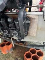
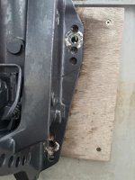
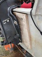
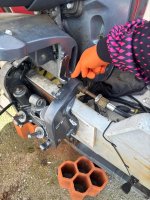
Yamaha 50GETO (62F) - Right side bracket / PTT removal stuck

tutis2002

Cadet
Thread starter
Joined
Nov 2, 2026
Messages
9
Hello everyone!

I am writing to the forum to seek guidance from anyone with experience in disassembling the Power Trim & Tilt (PTT) assembly on 3-cylinder, 2-stroke Yamaha outboard motors (models 50/60/70 HP, 62F / 6H3 block), specifically on a Yamaha 50GETO, model 62F, long shaft (L), serial number 504715.

My main objective is to extract the complete Power Trim unit to replace the electric motor (which has a broken, threaded shaft stuck in the block) and take the assembly to a workshop for extraction on a workbench. To achieve this, and based on what I have researched, it is necessary on my Yamaha motor to separate the arm that acts as the right side bracket.

So far, I have carried out the following steps according to the standard service procedure:

  1. Release of the central hydraulic: The manual valve for hydraulic bypass was turned, the tilt-lock pin/clip was removed, and the central pin of the main ram was taken out.
  2. Trim side bolts: The 6 side bolts of the Trim body have been removed (3 on the left side and 3 on the right side).
  3. Anode and brackets: The lower sacrificial anode was disassembled, and its fastening bar/bolt was completely removed.
  4. Transom anchors: The 2 through-bolts securing the right side bracket/arm to the transom plate have been completely removed.
  5. Steering connection: The steering was released by loosening and completely removing both the nut securing the cable housing and the threaded nut connecting it to the right arm of the motor.
  6. Electrical connections: The blue and green wires at the relay box and the lower ground terminal were disconnected.
Once all the above elements are removed, the right side bracket remains physically attached to the structural body—meaning it won't budge at all.

Reviewing the service manual's exploded diagrams (Chapter 7, BRACKET UNIT), I do not see any additional bolts or threaded fixings that should hold both parts together at this point. Here is the link in case you need to download the manual: Manual Montaje YAMAHA 50 GETO 62F

I have applied heat and tapped it, but I cannot get it to separate. In this video for a model like mine, it seems to separate easily (you can turn on subtitles and auto-translate): YouTube Video

As you can see, I need help because I don't know how to make the right side bracket move freely outward. I am unsure if there is an internal circlip, seal, collar, or pin that is not visible at first glance and continues to hold the arm back.

I know that seizing due to galvanic corrosion is common in the swivel tube / bushing area on this series of Yamaha engines, but I have applied heat with a heat gun and struck it with a nylon mallet, and I still can't get it to budge.

Before trying something more aggressive—like placing a jack between both arms and applying slight pressure—I wanted to know if anyone has encountered this problem and how they solved it.

I am sending you a link with a PDF containing images and the steps I have taken so far: PDF with images
Best regards to everyone, and thank you very much in advance for your help!
 

boscoe99

Commander
Joined
Aug 22, 2013
Messages
2,419
Have you tried to remove the trim and tilt unit from the motor without removing the clamp bracket? In a number of Yams this will work.

Disconnect the electrical leads. Trim the motor fully upwards and lock the motor in place. Remove the upper piston attach parts from the motor. Trim it fully inward. Remove the lower fasteners. Slide the trim and tilt unit out.
 

boscoe99

Commander
Joined
Aug 22, 2013
Messages
2,419
When it comes to loosening a clamp bracket you may find that sealant is holding it in place.
 

tutis2002

Cadet
Thread starter
Joined
Nov 2, 2026
Messages
9
Thanks for the feedback!

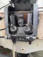
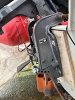
Regarding sliding the Trim & Tilt unit out without removing the clamp bracket: on my specific Yamaha 50GETO model (62F block), it is physically impossible to extract the PTT unit with both clamp brackets in place. The body of the electric motor and the hydraulic reservoir strike the inner frame of the right clamp bracket—there is simply not enough side clearance to tilt, angle, or slide the assembly free without spreading or removing that right arm.

As for the sealant on the transom: I have spent quite a bit of time scraping and cleaning away all sealant residue from every accessible area where the bracket contacts the transom plate.

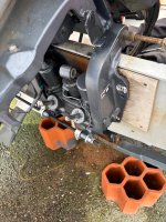
I am attaching a few images so you can see the current state, the lack of side clearance, and the contact points I have already cleared.
 

Attachments

  • WhatsApp Image 2026-11-02 at 17.58.41 (3).jpeg
    WhatsApp Image 2026-11-02 at 17.58.41 (3).jpeg
    1.7 MB · Views: 4
  • WhatsApp Image 2026-11-02 at 17.58.41 (1).jpeg
    WhatsApp Image 2026-11-02 at 17.58.41 (1).jpeg
    1.5 MB · Views: 3
  • WhatsApp Image 2026-11-02 at 17.58.41.jpeg
    WhatsApp Image 2026-11-02 at 17.58.41.jpeg
    1.5 MB · Views: 3

tutis2002

Cadet
Thread starter
Joined
Nov 2, 2026
Messages
9
In the photos, you can see the marks from driving a screwdriver in and tapping it with a hammer to separate the bracket and prevent any friction between it and the wooden backing plate it rests on... In addition to clearing out all the sealant from the entire area, at least as far as I could reach.
 

boscoe99

Commander
Joined
Aug 22, 2013
Messages
2,419
All Yamaha 2 stroke 50's are not the same. What is the year of the motor?
 

tutis2002

Cadet
Thread starter
Joined
Nov 2, 2026
Messages
9
All Yamaha 2 stroke 50's are not the same. What is the year of the motor?
It is a 2001 model.

The full ID tag on the clamp bracket reads:

  • Model: Yamaha 50GETO (62F block, Long shaft)
  • Year: 2001
  • Serial Number: 504715
The link I provided to the PDF file contains photos and the engine's identification plate.
 

tutis2002

Cadet
Thread starter
Joined
Nov 2, 2026
Messages
9
What if I try placing a hydraulic jack between both clamp brackets and applying gentle pressure? Or maybe it would be safer to use some kind of screw-based puller/spreader that pushes between both arms with every turn of the nut?

If I go with either option, I plan to place hard wooden blocks between the tool and the inner face of the brackets to distribute the force evenly and avoid cracking or marking the cast aluminum.

What do you guys think? Is this a safe and effective way to break the galvanic corrosion bond, or could the cast aluminum still be at risk?
 

99yam40

Fleet Admiral
Joined
Sep 7, 2008
Messages
9,375
maybe it is just me, but I do not see how galvanic corrosion bond could happen between the wood and aluminum
 

tutis2002

Cadet
Thread starter
Joined
Nov 2, 2026
Messages
9
maybe it is just me, but I do not see how galvanic corrosion bond could happen between the wood and aluminum
Well, the galvanic corrosion part—and maybe I didn't explain myself clearly in my previous messages when writing in English—would actually happen at the upper area, right at the detail shown in the photo, which is the exact reason why the arm won't separate. In any case, thanks for the joke; at least someone is reading my problem.
 

Attachments

  • WhatsApp Image 2026-09-06 at 12.21.09.jpeg
    WhatsApp Image 2026-09-06 at 12.21.09.jpeg
    1.3 MB · Views: 4
  • WhatsApp Image 2026-11-02 at 17.58.40 (1).jpeg
    WhatsApp Image 2026-11-02 at 17.58.40 (1).jpeg
    1.4 MB · Views: 4

tutis2002

Cadet
Thread starter
Joined
Nov 2, 2026
Messages
9
Here is the setup I've put together using a high-tensile threaded rod passed through the lower manual tilt pin holes to act as a spreader/puller.

The plan is to push the seized right-side bracket outward without damaging the aluminum:

  1. Left side (Fixed anchor): The outer nuts on the left side are locked together against the washer to hold the rod firmly in place so it won't spin or slide.
  2. Right side (Outer nuts): Obviously, the outer nuts on the right side will be loosened and backed off completely so they don't block the bracket from moving outward.
  3. Right side (Inner nuts - The push): I will progressively tighten the inner nuts (located between the PTT unit and the inside face of the right bracket). As I turn them, they will push against the washer and force the right bracket outward to the right.
I plan to apply just enough preload tension down here while using controlled heat and light taps up at the seized upper pivot area so the bracket slides off evenly without bending or stressing the aluminum.
Before I actually start cranking on the nuts and putting load on the bracket, what do you guys think of this setup? Do you see any red flags or potential weak spots pushing from down here, or am I good to go?
 

Attachments

  • 03 Extractor Motor Yamaha.jpg
    03 Extractor Motor Yamaha.jpg
    323.1 KB · Views: 0
  • 02 Extractor Motor Yamaha.jpg
    02 Extractor Motor Yamaha.jpg
    315 KB · Views: 0
  • 01 Extractor Motor Yamaha.jpg
    01 Extractor Motor Yamaha.jpg
    325.7 KB · Views: 0

tutis2002

Cadet
Thread starter
Joined
Nov 2, 2026
Messages
9
Update / Correction on the Puller Setup:
I realized I made a mistake in my previous photo regarding how the nuts were positioned. With the left-side anchor nuts placed on the outside of the left bracket, the threaded rod would simply slide to the left instead of pushing against anything.
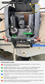
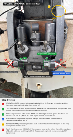
To make the puller work properly under compression between both arms, both working nuts must be placed on the inside faces of the brackets. I am attaching an updated diagram showing the exact setup and the step-by-step procedure I will follow so the bracket comes off safely without cracking the cast aluminum:
Step-by-Step Procedure:
  1. Remove outer nuts (marked with red X): Remove the outer nuts on both sides. They serve no purpose on the left, and the ones on the right will block the bracket from sliding out.
  2. Left side (Fixed anchor): Place a large washer, Nut A, and a locknut against the inside face of the left clamp bracket. Since this bracket is still bolted to the transom, it will safely absorb the reaction force.


  3. Right side (The pusher): Place a large washer and Nut B against the inside face of the right clamp bracket. Grease the rod threads and the washer face here to reduce friction. Only turn Nut B (1/8 of a turn at a time) using a standard wrench—no cheater bars or impact guns.
  4. Compression push: As Nut B advances along the threads, it pushes the right bracket outward while the rod braces against Nut A under compression. (Note: Keep an eye on the rod; if it starts to bow/bend, stop immediately).
  5. Heat, oil, and taps between turns: Preload alone won't break galvanic corrosion. Between small turns of Nut B, apply penetrating oil to the upper tilt tube threads, heat the aluminum housing (not the steel shaft) with a heat gun, and give light taps near the upper pivot with a mallet. Repeat this cycle.
  6. Keep it parallel: Since the push is at the bottom and the seizure is at the top, check the gap periodically so the bracket doesn't ****/bind. If it opens wider at the bottom than at the top, back off Nut B slightly, let it settle, and work the upper pivot with more heat and taps before tightening again.
Thanks again for all the help! I'll update once I get it off.
 

Attachments

  • Extractor Modificación CLAUDE.png
    Extractor Modificación CLAUDE.png
    2.5 MB · Views: 1

tutis2002

Cadet
Thread starter
Joined
Nov 2, 2026
Messages
9
Need advice before I proceed: stuck right-hand clamp bracket + puller set-up (Yamaha 50GETO 62F, 2001)

I would like your opinion before I do anything else on the stuck right-hand clamp bracket. Here is where I am:

Done so far: PTT/trim unit released (manual tilt screw turned, central ram pin and circlip removed, tilt lock pin removed, lower anode bar removed, the 3 PTT bolts on each side removed, both transom bolts on the right bracket removed, steering cable nut loosened, and the nut that holds the right bracket on the pivot is off). The engine tilts freely by hand, so the swivel bracket moves. The right bracket simply will not slide off the pivot area at the top, and there is no visible gap between it and the motor side where I could get penetrating oil in.

Mistake in my first puller: I had the anchor nuts on the outside of the left bracket. Since a threaded rod can only pull, not push, the rod would just slide out instead of spreading the brackets. The first picture shows the corrected set-up I am planning: nut A + large washer + jam nut on the inner face of the left bracket (it stays fixed because that bracket is still bolted to the transom), and nut B + large washer on the inner face of the right bracket. Turning only B (1/8 turn at a time) would push the right bracket outward, with the rod working in compression between A and B. The outer nuts on both sides come off.

Heat and taps plan (second picture): heat gun at about 500-550 °C, 2-3 in from the boss and always moving, aiming for roughly 250-300 °F in the aluminium (not more than about 390 °F), checked with an IR thermometer. While it is hot: 1/8 turn on B, plus light radial taps around the boss with a nylon mallet, and axial taps from the left end of the pivot bolt if I can reach it. Penetrating oil once it has cooled to about 140-175 °F, so it gets drawn in as it contracts. The idea is to repeat this in cycles over several days.

What I need from you before I start:

  1. Does the puller set-up in the first picture look right to you, or do you see any flaw? I would rather not crack the casting.
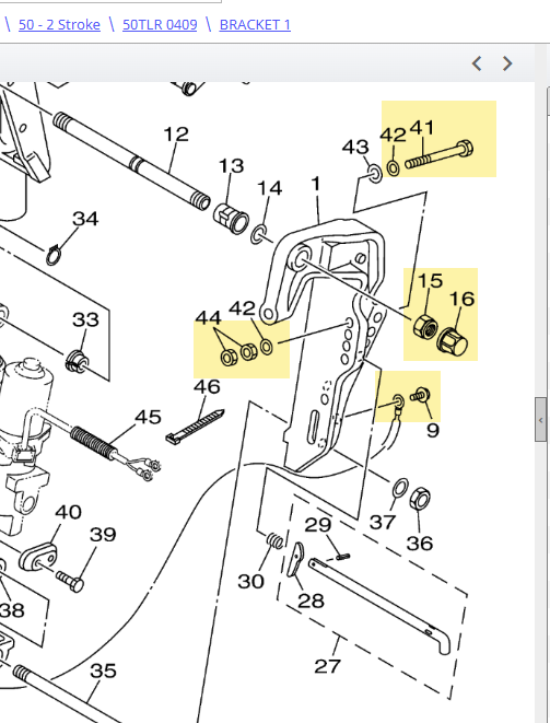
  2. In the “Bracket (Long transom)” exploded view of the 62F manual (page 7-8), the brackets pivot on the clamp bracket bolt (item 12) with the clamp bracket nut (item 10) at the other end. Has anyone had to drive this bolt out, and from which side?
  3. Is it safe to tap the end of that bolt along its axis, or is there a risk of damaging the bushings?
  4. Is the heat plan reasonable (temperature, distance, cycles), or would you do it differently? Any other tricks for a bracket seized by corrosion on the pivot, without a hydraulic jack?
I’m waiting for your comments and opinions before carrying out any of this. I really need your help, so thanks in advance.
 

Attachments

  • puller_setup_correct_EN.png
    puller_setup_correct_EN.png
    2.5 MB · Views: 1
  • heat_and_taps_pivot_zone_EN.png
    heat_and_taps_pivot_zone_EN.png
    2.4 MB · Views: 1
Top