wiring on 89 merc 115hp

jdogg#1

Cadet
Joined
May 27, 2009
Messages
29
just got a 89 mercury 115 hp and im getting no spark and trying to figure out the kill switch wires what wire goes to what
 

achris

More fish than mountain goat
Joined
May 19, 2004
Messages
27,468
Re: wiring on 89 merc 115hp

just got a 89 mercury 115 hp and im getting no spark and trying to figure out the kill switch wires what wire goes to what

Kill circuit wires are black/yellow... Disconnect it from the switchbox and recheck for spark...
 

jdogg#1

Cadet
Joined
May 27, 2009
Messages
29
Re: wiring on 89 merc 115hp

i just have the motor on a stand an the guy igot it from just cut the harness off so im a little lost. what do i do with the yellowand black wire.ground it or what
 

achris

More fish than mountain goat
Joined
May 19, 2004
Messages
27,468
Re: wiring on 89 merc 115hp

Grounding the black/yellow will stop the engine. In order for the ignition system to spark, the black/yellow must be open circuit. Be careful, because when the engine is running that wire has about 400 volts on it.... and it really hurts when it bites! :eek::eek:
 

achris

More fish than mountain goat
Joined
May 19, 2004
Messages
27,468
Re: wiring on 89 merc 115hp

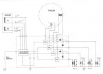
Now you need to start troubleshooting the ignition system. If you have a DVA meter great... Easy. If not, not so easy. We can do a few resistance checks. Refer to the circuit below....

attachment.php


Check that the 2 stator windings are not short to ground, and that they are also not open circuit, same with the triggers (although I consider it VERY unlikely you have both triggers out).

I'm in the process of designing a small and cheap add-on DVA adaptor for a standard multimeter. Stay tuned.
 

Attachments

  • 4 cyl ADI block (918 x 660).jpg
    4 cyl ADI block (918 x 660).jpg
    65 KB · Views: 0

achris

More fish than mountain goat
Joined
May 19, 2004
Messages
27,468
Re: wiring on 89 merc 115hp

it looks like the red wires are grounded

That's with them disconnected from the switchbox, yes....

That could stop spark. Check for spark with them disconnected. If you get spark, you're in for a new stator.... sorry...

Chris........
 

jdogg#1

Cadet
Joined
May 27, 2009
Messages
29
Re: wiring on 89 merc 115hp

no they werent disconnected the aren't groundd al looks good there
 

achris

More fish than mountain goat
Joined
May 19, 2004
Messages
27,468
Re: wiring on 89 merc 115hp

In that case it's time to break out the DVA.... With all wires connected to the correct terminals... While cranking check for 200-400 volts across the low speed stator (blue and blue/white). If you have that, then the problem is the switchbox.... If not, disconnect the blue and blue/white wires and see if you get anything across them while cranking.

Chris.... (still working on the DVA circuit)
 

jdogg#1

Cadet
Joined
May 27, 2009
Messages
29
Re: wiring on 89 merc 115hp

ok irechecked about 30volts with the blue wires connected and 250plus disconnected
 

Texasmark

Supreme Mariner
Joined
Dec 20, 2005
Messages
14,708
Re: wiring on 89 merc 115hp

gers out).

I'm in the process of designing a small and cheap add-on DVA adaptor for a standard multimeter. Stay tuned.

We just went through that last week: Diode rectifier with a preferred 1kv. Capacitor of .47 UF up to whatever suits you...seems 2.2 ufd electrolytic is common.....Leakage resistor of 1 or more Mohms, value not really critical.

Meter goes to the DCV scale. Diode rectifies the incoming pulsed bipolar signal, capacitor charges to the peak value, resistor keeps the capacitor bled down (slowly) so that if the incoming signal drops in value, the meter can measure it.

Mark
 

achris

More fish than mountain goat
Joined
May 19, 2004
Messages
27,468
Re: wiring on 89 merc 115hp

We just went through that last week: Diode rectifier with a preferred 1kv. Capacitor of .47 UF up to whatever suits you...seems 2.2 ufd electrolytic is common.....Leakage resistor of 1 or more Mohms, value not really critical.

Meter goes to the DCV scale. Diode rectifies the incoming pulsed bipolar signal, capacitor charges to the peak value, resistor keeps the capacitor bled down (slowly) so that if the incoming signal drops in value, the meter can measure it.

Mark

That exactly what I had in mind, just sitting down and doing the math for values. Then I'd do a nice drawing, and maybe some photos, so people here can build it....

I'll use a 1N4007, and a 'greencap' (1000v rating) and a resistor so the bleed off is about 3 seconds. All mounted in a small box, or even better, encapsulated in epoxy.

Still working on details... And a few (thousand) other things around the house, and fixing my boat, and some friends boats... Maybe this explains why I'm not getting a lot of sleep :D:D:D

Cheers,

Chris.....
 
Top