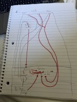
Wiring diagram, is it correct?

Joined
Feb 8, 2023
Messages
66
Hi guys,

I’ve spent the last hour trying to figure out the wiring for my 14 foot skiff. I’d like to have the switch panel in the stern (tiller drive) and the battery near the bow for weight distribution.

Here is the best I could come up with. I am struggling to understand the smartest way to do this… any guidance would be appreciated. Safety is always #1 priority
 

Attachments

  • 3E7ED1E1-EE76-4D0F-A547-4DF640EA00D2.jpeg
    3E7ED1E1-EE76-4D0F-A547-4DF640EA00D2.jpeg
    1.8 MB · Views: 20

alldodge

Moderator
Staff member
Joined
Mar 8, 2009
Messages
41,989
While the drawing is a bit messy looking I think I'm understanding what your wanting to do. Looks like most are lights and with that all the grounds could be tied together and run separate hots to each (except red/green)
 

havoc_squad

Senior Chief Petty Officer
Joined
Mar 5, 2011
Messages
738
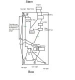
If you have the means to put a negative bus bar in the front of the boat that protects the wires from damage, that would be better than doing negative runs for each light in the front.

It makes it easier to diagnose and work on if this is possible to do.

I believe you are trying to do too much putting the battery in the front. That is going to make it several times more difficult to implement and it will cost you a LOT more in wire because you are going to have to run some very thick wire to do that depending on the amps calculated to be required in those wires.

If there is no starting battery setup with an outboard that can charge, I don't see any value in have a battery isolator/combiner. You would be better off with a standard marine manual battery selector switch.
 

Attachments

  • Electrical Distribution.jpg
    Electrical Distribution.jpg
    195.7 KB · Views: 10

dingbat

Supreme Mariner
Joined
Nov 20, 2001
Messages
16,039
Daisy chaining all the grounds and the power to the two nav lights reduces the number of wires running from bow to switch panel down to 3, GRD, NAV and LED.

Terminate “bow” and bilge GRD on battery.
Daisy chaining the power thru the switch panel reduces panel to battery and isolator to 1 wire.
 
Top