Wiring diagram for 12/24 trolling motor with 2 bank charger

hbuilder43

Cadet
Joined
Aug 28, 2007
Messages
13
I am continualling have problems with Motorguide 12/24 volt trolling motor. I seem to run one battery down after about 2 to 2 1/2 hours operation. Also, the shaft of the motor looks as if it is corroding badly! I have changed the wiring several times, bought another boat, and put the troll motor on new boat with the same results. Can you help?
 

Silvertip

Supreme Mariner
Joined
Sep 22, 2003
Messages
28,771
Re: Wiring diagram for 12/24 trolling motor with 2 bank charger

You probably heard the adage: Keep doing what you are doing wrong and you will keep doing it wrong! One battery is probably bad. Charge them up and then have them load tested. You said you changed the wiring several times. Changed it from what to what? Installed new wiring or did you changed how things were connected.

My thoughts on 12/24 volt motors is this: Eliminate the 12 volt feature as it was a rediculous feature in the first place. The motor operates more efficiently on 24 volts anyway. How do you do that you ask?

Look at the wires in the harness going to the motor. There will be three typically (red, black, and orange). Red-Black = 24 volts. Orange-Black = 12 volts. Below is the wiring for a straight 24 volt - two wire system. It doesn't matter if you have three or four wires running from the batteries to the panel at the front of the boat. (You didn't tell us what you have up there by the way but whatever that is will be bypassed.)

Wire your batteries like this. Any unused wires can simply be placed out of the way. Connect the +24 volt and ground wires from the batteries directly to the two terminals on the receptacle at the front of the boat to the terminals that feed the red and black wires going into the motor. Now go fishing. If you actually do have a switch panel up front it will now be inoperative.

24VTrollerWiring.jpg
 

hbuilder43

Cadet
Joined
Aug 28, 2007
Messages
13
Re: Wiring diagram for 12/24 trolling motor with 2 bank charger

Thanks for the response! The trolling motor plug has a 3 wire connection. This is a Motor Guide Brute that I added a new more powerful motor to. The problem existed before the motor replacement, and now still remain. I continually have to replace the speed switch, as the two lower speeds seem to burn out on the switch. I would like to go strictly 24 volt, but even the lowest speed is too fast on the 24 volt side.
 

Silvertip

Supreme Mariner
Joined
Sep 22, 2003
Messages
28,771
Re: Wiring diagram for 12/24 trolling motor with 2 bank charger

Depending on how the 12/24 volt selection is made (on the boat panel vs the switch on the troller) if you use 12 volts fairly regular, you may be using only one of the batteries which is why one runs down. Some systems break the series connection (24 volts) and parallel the two batteries for 12 volt operation which would then draw from both batteries. Tell us what your switch panel and wiring looks like and perhaps we can detect where the issue is. As for speed, try a prop with less pitch or one that is significantly smaller in diameter.
 

hbuilder43

Cadet
Joined
Aug 28, 2007
Messages
13
Re: Wiring diagram for 12/24 trolling motor with 2 bank charger

The trolling motor head has a 12/24 switch that handles the 12 or 24 volt selection. There is a rotary switch on the handle that selects the speeds forward and reverse.
 

Silvertip

Supreme Mariner
Joined
Sep 22, 2003
Messages
28,771
Re: Wiring diagram for 12/24 trolling motor with 2 bank charger

That's only part of the story. How many wires run from the batteries to the troller? The answer will be two, three or four. The answer will be two only if someone has mucked with the wiring.
 

hbuilder43

Cadet
Joined
Aug 28, 2007
Messages
13
Re: Wiring diagram for 12/24 trolling motor with 2 bank charger

That's only part of the story. How many wires run from the batteries to the troller? The answer will be two, three or four. The answer will be two only if someone has mucked with the wiring.

There are 3 wires to the plug at front console. 3 wires in the cable to the 12/24 volt switch on the head. Then more on the rotary switch. But I have found why the thing has burned up 2 lower speeds on rotary switch, there is 36 volts coming from the batteries. What I need is a diagram for Skeeter Limited Edition Dual Pro charging sysem. Thanks
 

Silvertip

Supreme Mariner
Joined
Sep 22, 2003
Messages
28,771
Re: Wiring diagram for 12/24 trolling motor with 2 bank charger

How do you get 36 volts from two 12 volt batteries? It isn't possible unless someone tied the starting battery in as well.
 

hbuilder43

Cadet
Joined
Aug 28, 2007
Messages
13
Re: Wiring diagram for 12/24 trolling motor with 2 bank charger

How do you get 36 volts from two 12 volt batteries? It isn't possible unless someone tied the starting battery in as well.

Well, that is why I need wiring diagram for Skeeter limited edition Dual Pro! The charger has cables the same size as battery cables and all of the wires go behind a firewall and connect to a bunch of breakers that are jumpered everywhere. This is a boat that I just bought, and I know nothing about it. One of the ground (black) cables has battery # 3 on it? I took my trolling motor off my older boat and put it on this one, and I think it has ruined it, because it turns backwards now!
 

Silvertip

Supreme Mariner
Joined
Sep 22, 2003
Messages
28,771
Re: Wiring diagram for 12/24 trolling motor with 2 bank charger

The title of this thread indicates you have a "two bank charger". Therefore, the electrical system for the troller was intended to be a 24 volt system. The motor will run backwards if polarity was reversed so the motor is probably not ruined. Good luck on finding a wiring diagram for the boat. Manufacturers didn't generally provide them. One look at most boat wiring is a good reason why. The geniuses that wired these things had no previous experience in electrical work. What you should do is concentrate on the troller side of the electrical system. Start at the plug and work backward. You can use the diagram I supplied earlier as a guide. Then follow the leads from the two bank charger and make sure they are attached to ONLY the two troller batteries. Check the starting battery connections. There should be four connections. Two large battery cables (black and red) should go to the engine. Red to the solenoid and black to the engine block. There should also be two smaller (probably #8 or 10 gauge red & black) wires on that battery. This is the "boat harness" which feeds the fuse/breaker panel. If you see another large ground cable going to one of the troller batteries, remove it. A complicating factor in all of this is if there is a dual battery switch. Then all of this takes a new twist but lets go at it assuming you don't have a switch. If I missed that it's because I do not re-read every long post. I'd get nothing else done. The fact remains, you cannot get 36 volts from two batteries no matter how they are connected. If you are measuring 24 volts red-black and 12 volts orange-black, that does not make 36 volts. It merely means you have 24 volts on one circuit and 12 on the other. That would be the normal situation by the way and as it should be.
 

KVH

Petty Officer 2nd Class
Joined
Mar 8, 2009
Messages
136
Silvertip: Wiring diagram for 12/24 trolling motor with 2 bank charger

Silvertip: Wiring diagram for 12/24 trolling motor with 2 bank charger

I'm having exactly the same problem with my Motor Guide 12/24.

I have four wires going back to the batteries. Something is plain wrong. Power lasts about 2 hours even though both batteries were fully charged by my charger. One hint of a problem: My charger shows one battery always weaker and charging more slowly, as if something is wrong. Both batteries are essentially new.

So, how do I change the wiring up front at the Bow Plug. Stratos, 201, 20' Bass Ski boat.

How do I eliminate that orange wire, if that's what you're saying?

Thanks for the help.
 

hbuilder43

Cadet
Joined
Aug 28, 2007
Messages
13
Re: Wiring diagram for 12/24 trolling motor with 2 bank charger

The title of this thread indicates you have a "two bank charger". Therefore, the electrical system for the troller was intended to be a 24 volt system. The motor will run backwards if polarity was reversed so the motor is probably not ruined. Good luck on finding a wiring diagram for the boat. Manufacturers didn't generally provide them. One look at most boat wiring is a good reason why. The geniuses that wired these things had no previous experience in electrical work. What you should do is concentrate on the troller side of the electrical system. Start at the plug and work backward. You can use the diagram I supplied earlier as a guide. Then follow the leads from the two bank charger and make sure they are attached to ONLY the two troller batteries. Check the starting battery connections. There should be four connections. Two large battery cables (black and red) should go to the engine. Red to the solenoid and black to the engine block. There should also be two smaller (probably #8 or 10 gauge red & black) wires on that battery. This is the "boat harness" which feeds the fuse/breaker panel. If you see another large ground cable going to one of the troller batteries, remove it. A complicating factor in all of this is if there is a dual battery switch. Then all of this takes a new twist but lets go at it assuming you don't have a switch. If I missed that it's because I do not re-read every long post. I'd get nothing else done. The fact remains, you cannot get 36 volts from two batteries no matter how they are connected. If you are measuring 24 volts red-black and 12 volts orange-black, that does not make 36 volts. It merely means you have 24 volts on one circuit and 12 on the other. That would be the normal situation by the way and as it should be.

Thanks for the reply! I suppose I will have to remove the oil reservoir and batteries in order to try to trace this wiring as you suggest. Just wish I could get a factory wiring diagram, because I don't understand all of the jumpers on what appear to breakers. If I could take a picture of this, would it be helpful?
 

Silvertip

Supreme Mariner
Joined
Sep 22, 2003
Messages
28,771
Re: Wiring diagram for 12/24 trolling motor with 2 bank charger

What are "all the breakers" you keep mentioning? The only breakers in the troller system are within a couple of inches or directly attached to the POS post of the batteries.

KVH - please do not jump into the middle of someone elses thread. We have enough confusion without adding to it. Start your own thread please.
 

hbuilder43

Cadet
Joined
Aug 28, 2007
Messages
13
Re: Wiring diagram for 12/24 trolling motor with 2 bank charger

What are "all the breakers" you keep mentioning? The only breakers in the troller system are within a couple of inches or directly attached to the POS post of the batteries.

KVH - please do not jump into the middle of someone elses thread. We have enough confusion without adding to it. Start your own thread please.

Not sure what they are, but they are breakers for the system. I will try to attach a picture sometime later that might explain what I am talking about. This system is not a simple 3 cables to the front with a dual charger hooked to 2 batteries pos to pos and neg to neg. All wires go behind a firewall, then connect to multiple posts that are jumpered to one another.
 

hbuilder43

Cadet
Joined
Aug 28, 2007
Messages
13
Re: Wiring diagram for 12/24 trolling motor with 2 bank charger

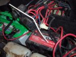
This is a picture taken with the bank of breakers (50 amp),removed from the "firewall". As you can see, the wires from the batteries, and the wires to the trolling motor receptacle are all on the back.
Maybe, you can see something that will help us both. I see in the lower left of the Dual Pro lid the name Charging Systems International. Do you think, I might be able to call them for a diagram?
Thanks for the help.
 

Attachments

  • wiring.JPG
    wiring.JPG
    74.8 KB · Views: 0

Silvertip

Supreme Mariner
Joined
Sep 22, 2003
Messages
28,771
Re: Wiring diagram for 12/24 trolling motor with 2 bank charger

The receptacle at the left side of the panel appears to be an AC socket into which you plug an extension cord to power the on-board charger at the dock. The cable off the back of that receptacle should go directly to the charger. If the charger you have is a two bank unit, it will have two outputs (probably two red and black pairs). Each pair of wires connects to each battery. Follow the red wire from the charger. Somewhere in that red wire you will find a fuse or circuit breaker. And I still don't see the "bank of breakers" you keep talking about. Are they perhaps under the black cover at the right side of the panel. Since I can't see the back side of the panel the picture is of no value. Raising the lid on whatever that squarish black thing is would help as well. A schematic of the on-board charger will not prove anything. The manufacturer has no idea how the unit would be installed as there are many variations so it would merely show the AC input and the two outputs connected to two batteries. What happens from there is the boat manufacturers wiring or who ever owned the boat before you. Here is a diagram of a "typical" 24 volt trolling motor system using a dual bank charger. And what in tarnation is the battery clip doing on the battery? A boat is not a place for that type of connection.

24VChargingSystem.jpg
 

hbuilder43

Cadet
Joined
Aug 28, 2007
Messages
13
Re: Wiring diagram for 12/24 trolling motor with 2 bank charger

Thanks for your help! Today, I removed the cables from the starting battery that were connected to the breakers on the back of the board in the picture. Then, I remove the wires from the battery charger. Apparently the past owner was trying to make the system charge the starting battery also. I Suppose it was wired for 24 volts and somehow the starting battery made a combination that ended in 36 volts to the plug in the front of the boat. I rewired the cables and breakers to make a 12/24 volt system at the front of the boat. I am sure the wiring is correct for that setup now, but the motor turns in reverse. There may be some connections reversed on the rotary switch that I am not aware of, or the trolling motor may be fried. Any thoughts? I don't have the charger connected at all now.
 

Silvertip

Supreme Mariner
Joined
Sep 22, 2003
Messages
28,771
Re: Wiring diagram for 12/24 trolling motor with 2 bank charger

I've gone as far as I can go with the available info.
 
Top