Jungleboat
Petty Officer 3rd Class
- Joined
- Feb 7, 2010
- Messages
- 78
Trust me, I DID search, all over the interwebs and then this forum search box - but am still not really sure...
Restoring an old boat, sourced an Evinrude engine for it (200 V6, pretty old). Now this engine comes with a remote throttle unit but it does NOT have the tilt and trim or ignition switch on the remote.
To make things worse, the engine owner did give me an ignition switch and key - and I've lost the switch! Been hunting for the last couple of days, no idea where it went. I do recall though that it had 4 pins on the back, and replacement switches at Cabelas etc also seem to be 4 pin.
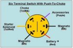
So presuming I get a new 4 pin switch - what exactly do I wire up to those 4 pins?
The boat has been previously stripped completely, no wiring remains and there never was a conventional ignition switch, else it would be an easy matter of reconnecting the existing wires.
You'd think this would be easy but page after page on the net presumes you already have the old wires or is written purely as search engine food but useless to human readers.
Surely there must be some basic, easy to understand universal wiring diagram for a 4 pin ignition switch, somewhere? Or can someone please just tell me what has to be wired to that switch?
Thanks!
JB


