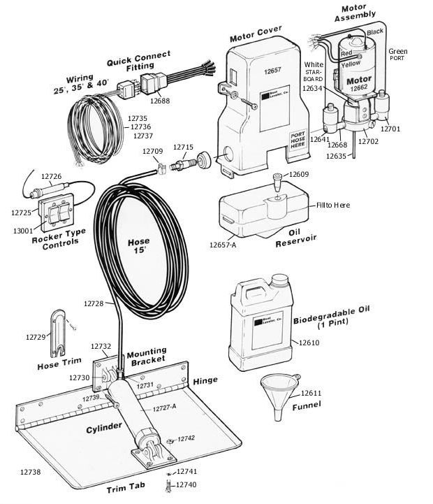
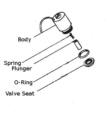
SO when i try to raise and lower my trim tabs only the port side will move. No matter which button I hit ( both port and starboard) the port one moves when either is pushed....starboard wont??? doesnt really make sense. Is this a wiring issue or a pump. cylinder issue. Thanks in advance.

- Shop
-
Main Menu Find The Right Fit
-
-
Slide Anchor Box Anchors Shop Now

-
Back Fishing
-
View All
- Fishing Rods
- Fishing Reels
- Fishing Rod & Reel Combos
- Fishing Tools & Tackle Boxes
- Fishing Line
- Fly Fishing
- Fishing Bait & Fishing Lures
- Fishing Rod Holders & Storage Racks
- Fish Finders, Sounders & Sonar
- Trolling Motors
- Fishing Nets
- Fishing Downriggers & Acessories
- Fishing Outriggers & Acessories
- Fishing Kayaks
- Fish Cleaning Tables
-
-
Minn Kota Riptide Terrova 80 Trolling Motor w/i-Pilot & Bluetooth Shop Trolling Motors

-
SportsStuff Great Big Marble Shop Tubes

-
Big Jon Honda 5hp Outboard Shop Outboards

-
Lexington High Back Reclining Helm Seat Shop Helm Seats

-
Kuuma Stow n Go BBQ Shop Now

-
Slide Anchor Box Anchors Shop Now

-
Back Electrical
-
View All
- Boat Wiring & Cable
- Marine Batteries & Accessories
- Marine DC Power Plugs & Sockets
- Marine Electrical Meters
- Boat Lights
- Marine Electrical Panels & Circuit Breakers
- Power Packs & Jump Starters
- Marine Solar Power Accessories
- Marine Electrical Terminals
- Marine Fuse Blocks & Terminal Blocks
- Marine Switches
- Shore Power & AC Distribution
-
-
ProMariner ProNautic Battery Charger Shop Marine Battery Chargers

-
Lowrance Hook2-4 GPS Bullet Skimmer Shop GPS Chartplotter and Fish Finder Combo

-
Boston Whaler, 1972-1993, Boat Gel Coat - Spectrum Color Find your boats Gel Coat Match

-
Rule 1500 GPH Automatic Bilge Pump Shop Bilge Pumps

-
Back Trailering
-
SeaSense Trailer Winch Shop Trailer Winches

-
Seadog Stainless Steel Cup Holder Shop Drink Holders

-
Slide Anchor Box Anchors Shop Now

-
- Boats for Sale
- Community
-


