ihaveabrownboat
Petty Officer 3rd Class
- Joined
- Aug 24, 2012
- Messages
- 88
Last thing to do on this boat project is adjust the trim limit switch. Have done it. Just not sure it's done correctly as the "out" switch by itself only brings the drive up from all the way bottomed out to about 1/3rd of the way up. To go higher than that have to use the "up" and the "out" switch together.
I was assuming the two switches didn't need to be used together until close to red area on the trim gauge. If that's not so I may be ok. Someone who actually knows what they're doing would be a big help here.
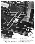
I've got the manual and following instructions that describe aligning the drive shaft housing to a point where its front edge is .75"-1" inside the gimbal ring. Must admit that description confuses me a bit though. Where on the drive shaft housing is the 3/4" to 1" measurement taken? It's at an angle compared to the gimbal housing so the depth varies.
If someone could explain in the most layman's of terms how I'll know how high or low to set the drive before setting the limit switch I'd feel much better about this. The old boat could go to the water tomorrow when this gets done. Last thing I'm just not comfortable with having correct.
Perhaps another way to go at this if I'm just too damn dumb to understand what may be simple illustrations to everyone else. Assuming the trim gauge is adjusted accurately where on the trim gauge scale would I open the circuit with the trim limit switch?
Thanks.


