Testing Nav/Anc switch

nemo2011

Petty Officer 2nd Class
Joined
Feb 15, 2011
Messages
157
Hello all!
I am having one biatch of a time getting my Nav/Anc lights to work properly!
so I thought I would start with the switch. power etc are all ok!
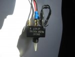
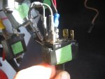
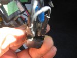
Is there a way to test this switch? to see if it is functional it is a paddle switch on-off-on
with 5 spade connectors on it.I have taken a few pictures and can post if it will help

I can get the bow and dash lights to work! (together)but can not get the Bow,Dash and Anc to come on together or just the Anc light to come on by itself.
any inputt would be greatly appreciated.:redface:
 

TSL812

Cadet
Joined
Jun 2, 2011
Messages
29
Re: Testing Nav/Anc switch

Did you check the bulb in the ANC light? Check for corrosion in the socket. After that I would check for power at the socket with a multi-meter or test light. If there's no power there I would make sure you have a good ground.
 

nemo2011

Petty Officer 2nd Class
Joined
Feb 15, 2011
Messages
157
Re: Testing Nav/Anc switch

No, the bulb is ok and it works when I connect power direct to grey Anc light wire!
 

nemo2011

Petty Officer 2nd Class
Joined
Feb 15, 2011
Messages
157
Re: Testing Nav/Anc switch

I have tried something similar to this schematic although my switch only has 5 spade connectors, the way mine was wired was red to middle spade bow and dash lights to top right spade and Anc light to bottom right.
the two at the left have a black wire running from one to the other and another black ground running tothe next switch.
the two spades at the left also are supposed to suply power to the switch light, I've fooled with it every which way to no avail, bringing me to believe it is a possibly bad switch!!!:confused:
 

TSL812

Cadet
Joined
Jun 2, 2011
Messages
29
Re: Testing Nav/Anc switch

No, the bulb is ok and it works when I connect power direct to grey Anc light wire!
Where did you connect to this wire, at the switch? Did you check to see if you are getting power at the terminal on the switch that the ANC wire is on with a meter or test light?
 

nemo2011

Petty Officer 2nd Class
Joined
Feb 15, 2011
Messages
157
Re: Testing Nav/Anc switch

Here are a few pictures of the Nav/Anc switch to give you a better idea of what's there!
The dash and bow light and Anc wires are not connected!
 

Attachments

  • IMG_4012.jpg
    IMG_4012.jpg
    126.1 KB · Views: 0
  • IMG_4013.jpg
    IMG_4013.jpg
    127.3 KB · Views: 0
  • IMG_4014.jpg
    IMG_4014.jpg
    124.6 KB · Views: 0

nemo2011

Petty Officer 2nd Class
Joined
Feb 15, 2011
Messages
157
Re: Testing Nav/Anc switch

Where did you connect to this wire, at the switch? Did you check to see if you are getting power at the terminal on the switch that the ANC wire is on with a meter or test light?
I hooked it up at the switch! bypassing the switch.
I used a light as well as a ammeter
 

TSL812

Cadet
Joined
Jun 2, 2011
Messages
29
Re: Testing Nav/Anc switch

Did it just stop working one day? Does it light up with the dash lights or when the switch is on? Which terminals had power when you tested it?
 

riptide09

Petty Officer 1st Class
Joined
Sep 11, 2009
Messages
297
Re: Testing Nav/Anc switch

You haven't stated if you actually tested the switch. You have power to the switch, we know that much. Flip the switch to the anchor position or all lights on. Throw a meter on the terminal going to the stern light and see of there is voltage. No voltage and the switch is bad.

Another way is to swap the wires for the bow and stern lights on the switch. If the stern light is working and now the bow light is not it is most likely a bad switch.
 

nemo2011

Petty Officer 2nd Class
Joined
Feb 15, 2011
Messages
157
Re: Testing Nav/Anc switch

You haven't stated if you actually tested the switch. You have power to the switch, we know that much. Flip the switch to the anchor position or all lights on. Throw a meter on the terminal going to the stern light and see of there is voltage. No voltage and the switch is bad.

Another way is to swap the wires for the bow and stern lights on the switch. If the stern light is working and now the bow light is not it is most likely a bad switch.

I am confused by the wires on the spades on the blue side of the switch one wire runs in a loop back to itself and the other runs to the spade (blue) from there there is a ground wire running to other switches.
I will see if I can get continuity between the two spades on the side marked (blue)
 

TSL812

Cadet
Joined
Jun 2, 2011
Messages
29
Re: Testing Nav/Anc switch

I would un-hook everything except your 12v source then use your test light to figure out which terminals have power with the switch in each position.

It looks like you have two terminals grounded which doesn't seen right. I think only one terminal should be ground for the light in the switch. It's hard to tell in the pics but are those diodes in the loops?
 

nemo2011

Petty Officer 2nd Class
Joined
Feb 15, 2011
Messages
157
Re: Testing Nav/Anc switch

I would un-hook everything except your 12v source then use your test light to figure out which terminals have power with the switch in each position.

It looks like you have two terminals grounded which doesn't seen right. I think only one terminal should be ground for the light in the switch. It's hard to tell in the pics but are those diodes in the loops?
Just to let you know that all lights were working fine untill about two weeks ago when I noticed my front bow lights were not working this was a case of corrosion cleaned up and got it working ok. Then noticed a wire was off one of the spades so seeing a empty spade I just pluged it in. thats when the trouble started.
I unplugged everything and connected the red to the middle spade on the three spade side turned switch to anc. and had power to one spade, turned switch to Nav and had power to the other spade on the same side as the red power.
I checked for continuity between the two spades that are connected by the looped black wire it was OK but checking for voltage on the spade connected by the black loop wire there was none

are you reffering to the little bumps at the tops of the two black looped wires, I really don't know what they are but thats the way it came from the factory mind you it is a 1989 boat so I doubt if they would have a record of how it was wired I did look at all the manuals recieved with the boat but no schematics just some wire color coding stuff!
this thing is starting to pee me off!!!:mad:
also I cannot seem to be able to get the ilumination on the switch to come on!
 

Outsider

Lieutenant Junior Grade
Joined
Apr 24, 2007
Messages
1,022
Re: Testing Nav/Anc switch

As mentioned, check continuity of each end with the power spade. You should have continuity with each spade opposite the direction of the paddle., but no continuity between the spades on the same end.

With that said and looking at the spades, the positive power supply should be connected to the middle spade and should supply power to both spades opposite the switch position. Connect both bow and anchor light feeds to one end, and a jumper from the anchor light feed to an empty spade on the other end. Be sure the anchor feed is on the end opposite the ANC switch position.

Ground wires from each light should go to a common ground, not to the switch.

What you should end up with is power to both lights when in the 'nav' position,, and only power to the anchor light in the 'ANC' position (thru the jumper). That's what the schematic is showing, although you have only one power spade ... www.cmsquick.com/Circuit6.jpg
 

nemo2011

Petty Officer 2nd Class
Joined
Feb 15, 2011
Messages
157
Re: Testing Nav/Anc switch

My bow lights(grey) and dash Lights(blue) are connected and on a female spade. the Anc light(grey) is separate on a female spade.Are you saying to connect these all together to go to one spade?
 

Silvertip

Supreme Mariner
Joined
Sep 22, 2003
Messages
28,771
Re: Testing Nav/Anc switch

Fourteen posts and this still isn't resolved?? Try these diagrams. This switch doesn't have an indicator light but the only additional connection would be a ground for that indicator. I've included a diagram for that circuit as well. Stop just moving wires around and figure out what wire comes from the bow and which one comes from the stern. Now connect them as shown. There should be no terminals with more than one wire except to power the instrument lights and that should happen only when the switch is in the NAV position. You don't need the instrument lights on when anchored and the ANC position is selected. The center pole of the switch is for +12 volts IN. The tab sticking out of the back corner of the switch is the ground connection for the indicator light. It looks like
the two black jumpers with diodes in the middle are needed for the indicator light as it must be ON in either position of the switch while the bow and stern lights do not.

NavSwitchWiring.jpg


LightedSwitchWiring.jpg
 

TSL812

Cadet
Joined
Jun 2, 2011
Messages
29
Re: Testing Nav/Anc switch

Which wire was unhooked, the ground? Try moving it to the open terminal on the side with two terminals. Then hook everything back up like it was. Keep in mind that the diodes have to face the right direction.
 

oops!

Supreme Mariner
Joined
Oct 18, 2007
Messages
12,932
Re: Testing Nav/Anc switch

did you try and hook it up the way tip suggested?.......that is the way.

also....the center post in pic 3 shows contamination at the block......

i havent been to campion is a week or so.....if i remember...i will swing by and get color codes......but the way tip has suggested in his diagram is correct.
 

nemo2011

Petty Officer 2nd Class
Joined
Feb 15, 2011
Messages
157
Re: Testing Nav/Anc switch

did you try and hook it up the way tip suggested?.......that is the way.

also....the center post in pic 3 shows contamination at the block......

i havent been to campion is a week or so.....if i remember...i will swing by and get color codes......but the way tip has suggested in his diagram is correct.

I really would like to know how the two black wires with diodes come into play and for what purpose.
My switch has only 5 spades on it , in tips diagram there are 6!
when I check for power should there be power at either spade on the two spade side?
 

TSL812

Cadet
Joined
Jun 2, 2011
Messages
29
Re: Testing Nav/Anc switch

I really would like to know how the two black wires with diodes come into play and for what purpose.
My switch has only 5 spades on it , in tips diagram there are 6!
when I check for power should there be power at either spade on the two spade side?
Neither of those diagrams really apply to the switch you have. The diagram showing how to use a 3 prong switch would be better for your situation.

On your switch the 2 prong side is power and ground for the light in the switch. The reason you have the diodes is to keep the nav lights from coming on when you have the anc light on.

On the 3 prong side....
Center post should be 12v feed. the connector with the diodes coning out of it should go on the terminal that has power when the switch is in the nav position. Then one diode should go to the other prong (one with power in the anc position). The other diode will go to the terminal beside it (on 2 post side). The ground wire goes to the other terminal on the 2 post side. Then your bow/dash lights will hook to the terminal that is attached to the connector on the nav side and your anc light will go to the connector on the post that is powered in the anc position.

Hope this helps, I'll try to make diagram for you if needed.
 
Top