tach signal characteristics

jrs151

Seaman
Joined
Apr 12, 2007
Messages
52
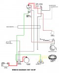
Can anyone offer me a definitive answer on the nature of the tachometer signal for most outboards?? Take an Evinrude for example, wherein the regulator rectifier supplies the gray wire (tach signal). I'm asking because I don't have an o-scope nor a running engine to test this myself at the moment.
Basically from what I can gather, this wire simply pulses a voltage potential that the tach gauge "counts" and thus factors an RPM reading. No need to dive into number of poles, etc... I got it. So my question are :

- these voltage pulses ... are they DC 0v-+12v ?? or are they AC -12v-+12v ??
- Sine wave or square wave?
- Does that line require "pinning" to ground as I see some discussions referring to connecting a pull-down resistor.
- Other discussions say this "signal" is just a tap off of the AC side of the regulator ? is it really JUST that simple and basic?

So, anyone know what this tach signal looks like?
 

boobie

Supreme Mariner
Joined
Nov 5, 2009
Messages
20,826
Re: tach signal characteristics

All I can tell you it's AC pulses taken off of the stator. Those tachs don't like DC voltage.
 

F_R

Supreme Mariner
Joined
Jul 7, 2006
Messages
28,226
Re: tach signal characteristics

You didn't specify a particular engine, so about all we can do is give you a generic answer. The stator under the flywheel generates an AC voltage which is fed to the rectifier which converts it to DC to charge the battery. It is a sine wave, I presume as positive and negative with respect to ground, but I can't say if it is a bit modified or not. I don't have an o'scope either. Some are single phase (two AC wires) going to a 4 diode bridge rectifier, and some are three phase (three AC wires) going to a 6 diode rectifier. The tachometer receives that sine wave via the grey wire (connected to one leg of the AC rectifier input) and counts the pulses.
 

Attachments

  • Wiring 1967 60hp fr.jpg
    Wiring 1967 60hp fr.jpg
    128.7 KB · Views: 5
Last edited:

boobie

Supreme Mariner
Joined
Nov 5, 2009
Messages
20,826
Re: tach signal characteristics

F_R, I think he has a later model motor than a '67.
 

F_R

Supreme Mariner
Joined
Jul 7, 2006
Messages
28,226
Re: tach signal characteristics

F_R, I think he has a later model motor than a '67.

Well, I assumed that was a possibility, but I posted that one because it is the very basic generic charging circuit.
 

Barnacle_Bill

Admiral
Joined
Feb 8, 2004
Messages
6,469
Re: tach signal characteristics

FR is right on. I have very little 4 stroke experience but I would assume they are the same. And Yes JRS it is really just that simple.
 
Last edited:

boobie

Supreme Mariner
Joined
Nov 5, 2009
Messages
20,826
Re: tach signal characteristics

But on his system I don't believe the tach wire comes off of the coil from the breaker points.
 
Last edited:

jrs151

Seaman
Joined
Apr 12, 2007
Messages
52
Re: tach signal characteristics

You didn't specify a particular engine

Yeah, forgot to mention the year into my OP, but yes I'm talking more modern methods. The specific OB I have is a 98 V4 looper 90 HP 60 degree. I note that nowadays most MFR's are generating the tach signal from the regulator/rectifier. So my question was pretty much what "type" of signal that is exactly. I'm leaning towards it being an analog +-12V sine wave, aka tap right off the stators AC circuit, albeit with perhaps a resistor to prevent excess amps traveling into the tach gauge, etc... I believe boobie has offered me what I'm looking for (thanks!).


FWIW, I'm kicking around the concept, as a proof of concept, of implementing a FH022AA regulator (commonly found on Yamaha motorcycles), and there is obviously no tach wire - LOL, so I'd have to add some circuitry to supply the tach.

Ok ... elephant in the room ... why would I want to do this ?? Well, in my "other" hobby - motorcycles (and in conjunction with my electronics knowledge) - I've come to know that MOSFET-based shunt regulators are way way "better" than SCR-based shunt regulators. Most-certainly the OEM regs on these outboards are SCRs. So given that we can all agree shunting an induction coil is the preferred method of regulating power from a PMA source (permanent magnet alternator), then what makes the MOSFETs better than the SCR's is the smaller "voltage drop" during the shunted periods. Although the SCRs shunts current back to the stator, it does this by becoming fully conductive, aka a short back to the stator (again, this is correct methodology), BUT the issue is that SCRs are not a pure short, thus resist up to 1v ? which we call voltage drop, and that's the IEEE way of saying Power consumption! When you math-out ohms law for Power (volts * amps = watts) you'll confirm that SCR regs will waste somewhere around a 55 watt light-bulb's worth of energy, which MUST be dissipated by the reg, hence is why on my engine it is submerged into the water jacket (at the top).

By contrast, the MOSFET regs fundamentally shunt as well (nothing different there), BUT the voltage-drop is more like down around 0.2v - which is significantly less. In fact, the FH022AA (being rated up to 50 amps max) runs very cool to the touch, meaning it can be easily mounted outside the engine block somewhere, thus intake air being drawn into the cowl would be more than enough to keep it cool. Furthermore, MOSFET reg do not need a reference voltage (aka battery, aka note the purple wire going back to the reg) in order to regulate voltage. Rather they internal regulate much better and consistent in holding that 14-14.4v charging state.

That all said, no I don't NEED to replace my Evinrude's regulator. Yet I wouldn't mind less power drawl on the stator, by running a better regulator and just simply put a blank ?cover? where the old one was.
 

F_R

Supreme Mariner
Joined
Jul 7, 2006
Messages
28,226
Re: tach signal characteristics

But on his system I don't believe the tach wire comes off of the coil from the breaker points.

OK, I apologize for that. I was trying to describe a generic charging circuit, and didn't pay any attention to the grey wire on the old diagram. But I did mention in my text that the grey tach wire comes off one leg of the AC circuit. Bad choice of diagrams.

Anyhoo, this discussion has gotten way more complicated than the original question implied. I don't have a clue what he is saying now.
 

boobie

Supreme Mariner
Joined
Nov 5, 2009
Messages
20,826
Re: tach signal characteristics

When you mention O-Scopes I don't either. I used them years ago on automotive but never on an outboard. Sorry, but I don't understand the jargon either. Just remember " mountains out of mole hills".
 
Last edited:

Chris1956

Supreme Mariner
Joined
Mar 25, 2004
Messages
28,000
Re: tach signal characteristics

jrs, The water-cooled voltage regulator on your motor is a very good one. Why do you want to change it?
 

submariner1980

Petty Officer 3rd Class
Joined
Mar 7, 2010
Messages
84
Re: tach signal characteristics

The signal for tachometer is simple half wave rectified sinusoidal 0 - +12v.Half_Wave_Rectifier_Circuit.gif
For the rectifier - regulator you have mention you should connect tah wire thru single diode to the coil. I have done this on my Evi 70 1976. Any question PM me but will be out for few days.
 
Last edited:

daselbee

Commander
Joined
Jan 20, 2009
Messages
2,765
Re: tach signal characteristics

The signal for tachometer is simple half wave rectified sinusoidal 0 - +12v.View attachment 219670
For the rectifier - regulator you have mention you should connect tah wire thru single diode to the coil. I have done this on my Evi 70 1976. Any question PM me but will be out for few days.

I question this info. The tach signal on his engine is tapped directly from the stator, on this engine it is a single phase AC signal that obviously varies both in voltage AND frequency as the engine RPMs change.

There is absolutely NO diode to create a half wave signal, unless it exists within the tach itself. If it exists within the tach, that in no way changes the electrical characteristics of the signal from the stator. Very good point about the current limiting issue. If the grey tach wire is somehow shorted to engine ground.....SMOKE!

I do not know if the output of the stator is a true sine wave. It is more likely a sinusoidal wave, (not true sine wave but similar) because we are in fact only charging a battery here....nothing rocket science about that.

I have a scope and will see if I can get pics to post up here. It is an old school Tektronics, and I will have to try to take a pic of the scope screen with my cell phone in the SUNlight....it will be iffy. Also I cannot do it until tomorrow.....

It would be great to re-design this reg/rect with better components. I personally would like to see an added output of the reg/rect regulated at 12v, that is isolated from the normal battery charging output. You could then use that 12v output to drive any number of devices, and when the engine stopped, no power goes to those devices. First and foremost would be an electric fuel pump. This would free up multitudes of ppl from having to buy a 450 buck VRO/OMS.
 

Chris1956

Supreme Mariner
Joined
Mar 25, 2004
Messages
28,000
Re: tach signal characteristics

Dasel, To safely run that elec fuel pump, could you take the tachometer signal, put it thru a diode, and then a DC-DC converter to stabilize the voltage and then drive a small relay for the fuel pump? The relay would also need to be powered from the Starter solenoid wire, for starting the motor. You will want a diode on the solenoid wire to prevent the starter solenoid from being powered when the fuel pump is on.
 

WernerF

Petty Officer 1st Class
Joined
Sep 5, 2011
Messages
320
Re: tach signal characteristics

In the rectifier-only engines one of the four diodes does work as an half wave rectifier for the tach signal. You can consider the waveform as a half wave rectified sine of a much higher voltage, but clipped at battery voltage. In fact the peaks voltages are one diode drop lower and higher respectively.
TachCircuit.jpg
The regulators put out a more square shaped signal, the peak voltage is a little lower, about 8V. The pulse width can vary with regulation range, 50% duty cycle when full charging, but less when current is reduced. This is a low power signal (short circuit proof), so you cannot load it to operate a relay or so.

jrs151, you CAN use MOSFETs for shorting the stator coil, and heat dissipation will be considerably lower and cooling easier or even not necessary. But the over-all losses are dominated by far by the stator resistance. The stator temperature won't drop.
The second point is that you want to short an inductance and the great thing about SCRs is that they inherently stop conducting when the CURRENT is zero. With MOSFETs you need a shunt resistor in order to detect the current zero-cross. If you switch off the MOSFETs while there is still current in the stator, the stator will answer with a great voltage peak.
 

daselbee

Commander
Joined
Jan 20, 2009
Messages
2,765
Re: tach signal characteristics

That's exactly what I am thinking.
I don't know about using the grey wire to half wave rectify it. Once I look at the signal on both the two yellows and the grey wire with ref to engine ground I will know more.

You would not need to DC-DC convert it I don't think. But you would need to regulate it somehow to keep it down to 12v for the relay coil. A 7812 regulator and a cap would be the key components. The relay should be able to handle a very ugly pick voltage. The fuel pump itself can run off the boat battery. All you gotta do is operate a relay with the circuit we are considering. It would really be great to have all this in the reg/rect package, tho.

And again, great thinking on the need to power it from the key switch until it gets running. You wouldn't even need a primer bulb....
 

daselbee

Commander
Joined
Jan 20, 2009
Messages
2,765
Re: tach signal characteristics

Very good, WernerF. Very good.

Oops...I said "Aero" should have read closer....WernerF it is.
 
Last edited:

jrs151

Seaman
Joined
Apr 12, 2007
Messages
52
Re: tach signal characteristics

Great to see some good discussions here. I was a little hesitant about posting this up because all too often people get stuck in there lanes and don't accept things that don't fit in a box.


In the rectifier-only engines one of the four diodes does work as an half wave rectifier for the tach signal. You can consider the waveform as a half wave rectified sine of a much higher voltage, but clipped at battery voltage. In fact the peaks voltages are one diode drop lower and higher respectively.
View attachment 219677
The regulators put out a more square shaped signal, the peak voltage is a little lower, about 8V. The pulse width can vary with regulation range, 50% duty cycle when full charging, but less when current is reduced. This is a low power signal (short circuit proof), so you cannot load it to operate a relay or so.

jrs151, you CAN use MOSFETs for shorting the stator coil, and heat dissipation will be considerably lower and cooling easier or even not necessary. But the over-all losses are dominated by far by the stator resistance. The stator temperature won't drop.
The second point is that you want to short an inductance and the great thing about SCRs is that they inherently stop conducting when the CURRENT is zero. With MOSFETs you need a shunt resistor in order to detect the current zero-cross. If you switch off the MOSFETs while there is still current in the stator, the stator will answer with a great voltage peak.


Werner - very good info here ! I suspected it might be a pulsed DC. Reading the OMC Service Manual, there's a diagnostic test looking for the 8V, so what you are saying makes a lot of sense. Unfortunately there is no halfwave ?tap? on the FH020AA, so I would have to circuit-up something with maybe a transistor & and maybe zener in order to get a "square-ish" DC wave produced.

You also bring up a good point about SCR resets. I really don't know what the internals of the FH020AA reg are, but I do understand that true the FETs will not clamp the phase to zero like SCR require. So, interesting about your spike reference. Is it possible that the circuit governing the MOSFET's gate is sensing the output (regulated) voltage rather than stator current regard when to unclamp the phase? Thus maybe the FETs unclamp more smoothly rather than immedaite feild collapse/rise - IDK, lol, but I can say that this reg is very smooth and kind on the electrical system ? aka sort of the Cadillac of regulators.


.....
It would be great to re-design this reg/rect with better components. I personally would like to see an added output of the reg/rect regulated at 12v, that is isolated from the normal battery charging output. You could then use that 12v output to drive any number of devices, and when the engine stopped, no power goes to those devices. First and foremost would be an electric fuel pump. This would free up multitudes of ppl from having to buy a 450 buck VRO/OMS.

daselbee ? what you are wishing for isn't really that hard ? and you wouldn't need a new regulator or isolated 12v power bus. A simple 13v Zener diode could be used to control a relay which powers-up your ?running-only? accessories. Without the engine running the system voltage hovers around 12.8v (aka normal battery levels). But when running, system voltage rises and triggers the zener's threshold, aka flipping the relay.

If that sounds to involved, there is a commercial product that does sort-of the same thing called "PowerSense Node". I actually use this on my motorcycle. I chose to just connected it to a relay, for which the relay powers up all my "toys". Engine running, all toys come alive. Stop engine, total power is physically removed - aka no risk of inadvertant battery or parasitic drains.
 

submariner1980

Petty Officer 3rd Class
Joined
Mar 7, 2010
Messages
84
Re: tach signal characteristics

You don't need to get a "square-ish" DC wave. It's work perfect with sine half wave.
 

WernerF

Petty Officer 1st Class
Joined
Sep 5, 2011
Messages
320
Re: tach signal characteristics

Is it possible that the circuit governing the MOSFET's gate is sensing the output (regulated) voltage rather than stator current regard when to unclamp the phase? Thus maybe the FETs unclamp more smoothly rather than immedaite feild collapse/rise - IDK, lol, but I can say that this reg is very smooth and kind on the electrical system ? aka sort of the Cadillac of regulators.

It's the voltage being above 14.4V that determines whether to switch on the FETs (or SCRs) at all. You can switch them on at any time because the stator inductance will slow current rise. Then the voltage will drop and if you switch off the FETs without waiting for the next current zero-cross the resulting spike will most likely been caught by the rectifier diodes and the battery. So not too bad. But better is to avoid the spike at all, like SCRs automatically do.
Unclamping smoothly doesn't work, because then the FETs would dissipate all the energy stored in the current of the stator inductance. They would get even hotter then SCRs would get.
Generally the battery will smooth out everything. The voltage rises and falls slowly. So the regulation scheme can be simple: stop charging when battery voltage is high, and restart charging when the voltage has dropped a little. The Cadillac approach (here in Germany we would say Mercedes) might be a phase angle control for switching on the FETs. But this could be done with SCRs also.
 
Top