rectifier -tach issue

lilmo

Recruit
Joined
Feb 18, 2014
Messages
2
hi everyone -quick question
having tach issues
my rectifier has 3 wires- red (battery) and two yellow wires (from stator I guess),.Tach was working but was coming and going. after looking at many schematics , they all show the gray wire on an outside post with yellow wire.... . I moved the gray tach signal wire from one yellow (middle post on rectifier) wire over to the other yellow wire and it started back workin. I had to readjust the pulse count to get it accurate- but it does work
my question is am I doing right- will this affect anything else? what exactly does rectifier do??
 

lilmo

Recruit
Joined
Feb 18, 2014
Messages
2
rectifier tach issue

rectifier tach issue

sorry if this is not right spot for this- im new.lol
hi everyone -quick question
having tach issues
my rectifier has 3 wires- red (battery) and two yellow wires (from stator I guess),.Tach was working but was coming and going. after looking at many schematics , they all show the gray wire on an outside post with yellow wire.... . I moved the gray tach signal wire from one yellow (middle post on rectifier) wire over to the other yellow wire and it started back workin. I had to readjust the pulse count to get it accurate- but it does work
my question is am I doing right- will this affect anything else? what exactly does rectifier do??
 

merc850

Commander
Joined
Jul 7, 2010
Messages
2,055
Re: rectifier -tach issue

The rectifier in that instance converts AC current to DC to charge the battery, while the engine is running 2500+ rpm connect a VOM set at +10v DC - red to positive terminal black to negative on battery, you should see +13v and as you increase rpm the voltage will increase if the charging system is working. Don't connect the tach to the red wire!
 

Frank Acampora

Supreme Mariner
Joined
Jan 19, 2007
Messages
12,004
Re: rectifier tach issue

Re: rectifier tach issue

Well, yes, you are in the wrong forum and would probably get a better answer from the correct forum of your engine brand. However you do deserve some sort of answer. The engine whether or not it is inboard or outboard has an alternator to supply electricity. The rectifier converts the Alternator's AC voltage to DC voltage. This keeps the battery charged and supplies the necessary voltage to run all the 12 volt DC appliances on the boat.

You may ask: Why use an alternator? Simple! Alternators are more efficient than DC generators and supply more and steadier voltage than an equivalent generator. If you have ever driven a 1950s car with a generator, you would see the headlights dim as you came to a stop because the generator produced less than 12 volts at idle.

I suspect you have an outboard because many of the inboard engines have built-in rectifiers in the alternator and tachometer signal is taken from the distributor (unless the engine is newer without a distributor.)

The two yellow leads from under the flywheel are AC to the rectifier. Alternating current is just that, it reverses periodically just like house current but frequency depends upon engine rpm and voltage is lower. Since it reverses, the tachometer does not care from which terminal it takes signal. So if the grey wire is signal, either terminal will suffice. And no, it should not affect other systems. HOWEVER: Frequently a malfunctioning tach will indicate a bad rectifier.

THUS: You need to check or replace the rectifier. With wires disconnected, check both AC terminals resistance to ground--it should be infinite and check both ways on the positive and negative terminals. They should have high resistance one way and low resistance the other.

Now , since you have also switched terminals and the tach seems to be functioning again, you also need to check the alternator (stator) to see if it is delivering voltage on both wires. You need to check the resistance across both wire and the resistance between each wire and ground. This will tell you if there is a broken wire or an internal short to ground.
 
Last edited:

Bondo

Moderator
Staff member
Joined
Apr 17, 2002
Messages
71,396
Re: rectifier tach issue

Re: rectifier tach issue

sorry if this is not right spot for this- im new.lol
hi everyone -quick question
having tach issues
my rectifier has 3 wires- red (battery) and two yellow wires (from stator I guess),.Tach was working but was coming and going. after looking at many schematics , they all show the gray wire on an outside post with yellow wire.... . I moved the gray tach signal wire from one yellow (middle post on rectifier) wire over to the other yellow wire and it started back workin. I had to readjust the pulse count to get it accurate- but it does work
my question is am I doing right- will this affect anything else? what exactly does rectifier do??

Ayuh,.... Welcome Aboard,.... Whatcha workin' on,..?? besides it's tach,....

Nevermind, I found yer other thread,...

Please read our postin' rules, 'n guidelines,...
Post yer question once, 'n only once, in only one forum,...

Thank you,....
 
Last edited:

achris

More fish than mountain goat
Joined
May 19, 2004
Messages
27,468
Re: rectifier tach issue

Re: rectifier tach issue

... THUS: You need to check or replace the rectifier. With wires disconnected, check both AC terminals resistance to ground--it should be infinite and check both ways on the positive and negative terminals. They should have high resistance one way and low resistance the other.....

You need to use the 'Diode check' function on a digital multimeter to check diodes properly. Forward biased they should read about 0.7v, reversed biased should show infinity. You can't properly check diodes using resistance.

There are 4 diodes in the rectifier, and you need to check all of them, in both directions.

Chris......
And for the smart people here (and I know there's a few of you ;)) these are silicon rectifier diodes, not germanium. Germanium would show about 0.3 volts drop across them...
 
Last edited:

achris

More fish than mountain goat
Joined
May 19, 2004
Messages
27,468
Re: rectifier -tach issue

Subsequent to my previous post I have put together a document on bridge rectifiers....

How to check a rectifier.

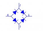
The rectifier on your outboard is a ‘bridge rectifier’ consisting of 4 silicon rectifier diodes, arranged in a ‘bridge’ pattern.

attachment.php


Let’s start with WHAT a diode is. Basically, a one way valve. It will allow current to flow in one direction but not the other. For those familiar with hydraulics it is exactly like a check valve. And just like a check valve it has a ‘cracking pressure’. In the case of these silicon diodes, that cracking pressure is about 0.7v, which means for us checking them, we need to use a meter designed to check diodes. The normal resistance measurements of a multimeter are not sufficient to check diodes. The ‘diode check’ function of a multimeter reads out the voltage drop around the diode being checked. We are looking for about 0.7v in the forward direction (the direction which allows flow) and infinity in the reverse direction. If the diode shows a short (0.00v) in either direction then the rectifier is faulty and needs to be replaced. Also if it shows infinity in both directions it’s faulty.

Explaining the circuit.

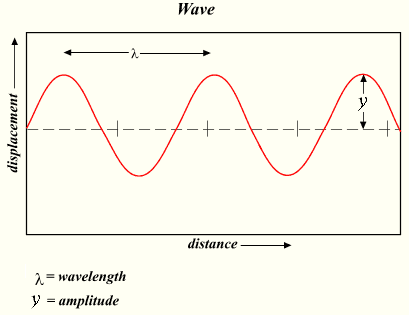
The circuit is quite a simple one. The stator (located under the flywheel) produces an alternating current... like this... (a ‘sine wave’)

Wave.png


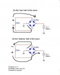
Using the diagram below (and the number on the rectifier as reference) here is basically how is work.

When the stator is in the half of the wave that has the current flowing ‘UP’ the page. The positive part of current will travel to the battery through diode ‘2-1’ and back to the negative side of the stator through diode ‘4-3’. Because diodes only conduct in a positive direction, the other 2 diodes will block the flow of current. When the current flows in the other direction (DOWN the page) diodes 4-2 and 3-1 will conduct and the other 2 will now block...

attachment.php


Testing.

To test a rectifier you need to remove all the leads from it. Using a multimeter set on the ‘DIODE’ function, check each diode in both directions. (On some rectifiers there are only 3 terminals. The metal mounting pad is the 4th terminal). To check the ‘negative’ diodes, put the red lead on the ground terminal (pin 4 in our drawing) and the black lead on each of the ‘AC’ terminals (where the yellow lead would connect), and you should see our 0.7v on the meter display. That can vary a little, between 0.6 and 0.8v. Now swap the leads, black on ‘ground’ and red on each of the ‘AC’ terminals. You should see infinity on the meter.

Now put the black lead on the ‘+’ terminal (where the red wire would connect) and touch each of the ‘AC’ terminals with the red lead. Again we should see around 0.7v. Swap the leads (Red lead on ‘+’) and touch each of the ‘AC’ terminals with the black, and we are looking for infinity.

If you have all these readings correct, then the rectifier has checked out correctly. If any one of these readings is wrong (either infinity or 0v where there should be 0.7, or 0v where there should be infinity) then the rectifier is faulty and needs to be replaced.

I hope this helps you out,

Chris......
 

Attachments

  • Rectifiers explained.jpg
    Rectifiers explained.jpg
    54.3 KB · Views: 1
  • rectifier.jpg
    rectifier.jpg
    16.1 KB · Views: 1
Last edited:
Top