Re: Protecting sensitive engine wiring while charging 24 volt trolling bank
Thank you all for your input. I also fired off an email to the tech rep at BEP Marine and the following is his reply.
Hello Jim,
I have to assume that the VSR you are using in this application is a 710-TBVSR? If that is the case then you have a 12V alternator on the engine and so the 710-TBVSR 'flip-flops' across its relays to alternately charge each of the 12v batteries in your 24v trolling bank?
There really is no risk to the vessels electronics from the 71-TBVSR. In the simplest sense the TBVSR is paralleling the start battery with the trolling bank batteries, each in turn, to charge them when the engine is running.
The red wire to be connected to the ignition outputs nothing but receives a voltage level signal that is used to tell the TBVSR when the alternator is running and so to begin charging. Also when the engine is shut down and the alternator is not charging the boats voltage will drop to the batteries rest voltage and the TBVSR will cease charging the trolling bank.
I hope this allays any concerns you might have.
Regards
Marcus
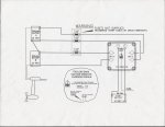
The wiring diagram supplied with the switch shows the input leads connected to the start batteries and the output leads to each of the trolling bank batteries through 70 amp fuses. The final wire is a small red wire that is connected to the ignition switch. That wire is the one my mechanic is so concerned about. Could any of you take a look at the diagram (posted on the BEP site) and tell me if you agree or disagree with the tech rep assessment?
Thank you