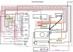
New Wiring Diagram completed today

Joined
Nov 5, 2009
Messages
27
Hopefully this will show up big enough for people to look at, I made a new wiring diagram last night for the whole boat using Paint and Word for Windows. Can some of you guys take a look and see if it looks okay for me?

Thanks!

Mike - mikes402jetboat
 

Attachments

  • Final diagram.jpg
    Final diagram.jpg
    143.9 KB · Views: 0

proaudioguy

Petty Officer 2nd Class
Joined
Aug 12, 2010
Messages
171
Re: New Wiring Diagram completed today

Well without tracing down the schematic I'd say it looks like you did a very thorough job and I'm impressed! Of course if you run into any issues you will easily be able to track them down now.
 

Silvertip

Supreme Mariner
Joined
Sep 22, 2003
Messages
28,771
Re: New Wiring Diagram completed today

Nice job. Although what you show looks correct, I don't see a neutral safety or kill switch in the ignition system. You also show the +12 volt bus going to the fuse panel from the alternator with no protection in that circuit. That line normally is powered either directly from the battery (or the Perko switch in this case) with a breaker or fuse within six inches of its source. Nothing wrong with coming off the alternator but again -- no protection. Without that protection the entire run to the fuse panel remains subject to a short and possible fire. Lastly, if this boat is equipped with an electric fuel pump I also do not see the oil pressure cut off for the pump. You do realize also that the NAV light switch must be a SPDT using a diode or a DPDT for proper NAV/ANCHOR operation. Those two wiring techniques are shown below. Since you show only part of the actual engine wiring, you would be advised to get a copy of the wiring diagram for your engine and outdrive. No sense re-inventing the wheel. Should it be necessary to have a shop work on this boat (or a new owner) the wiring would not be easily serviced thus running up the labor bill.

NavSwitchWiring.jpg


Nav-AnchorSwitch.jpg
 

fish_on_the_deck

Petty Officer 3rd Class
Joined
Jun 30, 2010
Messages
94
Re: New Wiring Diagram completed today

that is a complex schematic. I find it easier to follow if you split out the power distribution, the engine wiring harness and the gauge control signals onto separate diagrams... but whatever works for you.

I didnt look too hard at it (partly because of the complexity), but did notice youre using an awful lot of 10AWG. Usually thats pretty oversized for individual loads... even a bilge pump. no reason to use more expensive and difficult to run cable if you dont have to. your fuses are prohibiting using the max capacity of that cable anyway.:D
 

sasto

Captain
Joined
Jun 1, 2010
Messages
3,918
Re: New Wiring Diagram completed today

If she were mine I would install a ground buss in the engine compartment with a ground coming off my battery.....and attach my grounds to to the buss instead of the engine. I would also take the ground from the fuel sender to the gauge.

I also would follow Silvertip and fish_on_the_deck's advice.

Good Luck!
 

proaudioguy

Petty Officer 2nd Class
Joined
Aug 12, 2010
Messages
171
Re: New Wiring Diagram completed today

NavSwitchWiring.jpg


Just mentioning this for those that might wire the switch and mount it without checking first. The switch labels are upside down relative to the schematic using the back of the switch. The Anchor ON position would be at the top. When a toggle switch like this is switched UP, the center contacts are connected internally to the bottom contacts and vice versa. If you wanted the labels to match the picture you would have to reverse the top and bottom contacts from what the schematic says or just rotate the switch 180 degrees.
 
Top