my wiring diagram, does this look like it will work?

Joined
Jun 17, 2013
Messages
9
boat diagram.jpg
Does this look like it will work?
(click top thumbnail)
 

Attachments

  • boat diagram.jpg
    boat diagram.jpg
    18.8 KB · Views: 0
Last edited:

Don S

Honorary Moderator Emeritus
Joined
Aug 31, 2004
Messages
62,321
Re: my wiring diagram, does this look like it will work?

Try making the picture big enough to read.
 
Joined
Jun 17, 2013
Messages
9
Re: my wiring diagram, does this look like it will work?

Sorry about that, should work now
 
Last edited:

Auger01

Petty Officer 1st Class
Joined
Aug 15, 2009
Messages
201
Re: my wiring diagram, does this look like it will work?

That should work. Four guage is probably overkill for the console and trolling, but if you have a big spool of it, by all means use it.
 
Joined
Jun 17, 2013
Messages
9
Re: my wiring diagram, does this look like it will work?

I do haha. Thank you for your response. My main concern was that I saw that some people wired the main engine and trolling motors directly to their respective batteries, and wasn't really sure why. I'd like the ability to cut ALL power, and to charge my batteries independently with my 2 bank charger.
 

Don S

Honorary Moderator Emeritus
Joined
Aug 31, 2004
Messages
62,321
Re: my wiring diagram, does this look like it will work?

I agree as well that it looks fine. Just make sure your buss bars and distribution blocks are sized to handle the max amperage draw in your system (normally the starter).
Thanks for the larger picture as well.
 
Joined
Jun 17, 2013
Messages
9
Re: my wiring diagram, does this look like it will work?

the bus bar is rated at 150 amps, and the distribution block accepts up to 0 gauge wire, so I should be fine. Just in case I run out of the 4 gauge, what gauge would be acceptable for the trolling motor? It is a 55 lb minn kota riptide.
 

UncleWillie

Captain
Joined
Oct 18, 2011
Messages
3,995
Re: my wiring diagram, does this look like it will work?

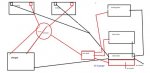
...My main concern was that I saw that some people wired the main engine and trolling motors directly to their respective batteries, and wasn't really sure why. I'd like the ability to cut ALL power, and to charge my batteries independently with my 2 bank charger.


The block is rated for 150 AMPs continuous, so the multi-hundreds of AMPs when you hit the starter for a few second will probably be OK.

When the Troller and the Engine Starter are OFF, the are just as OFF as if the Perko Switch was OFF.
The Dual Bank charger will never detect any difference.

The reason for direct wiring to the Batteries is all the losses in all the extra connections and wiring getting into and out of the Perko Switch and the Distribution Block.

Going through the switch adds complexity and gains nothing.
Using your schematic you will need to set the Perko Switch to...
#1 to start the motor.
#2 when starting to troll.
#1 again to restart the motor.

If you forget to re-position the switch...
Starting on #2 reduces your limited Trolling Time.
Trolling on #1 risks damaging the Non-Deep Cycle, Starting Battery.
Never Troll in BOTH. You will have no backup battery.

With the engine and Troller wired directly to their respected batteries...
The switch can be set to #1 Indefinitely and BOTH in the Rare event the Starting Battery becomes depleted.
The risk of forgetting to position the switch is eliminated.
 
Top