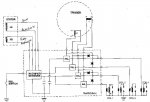
The electrical pickups under the flywheel consist of 3 sources: Battery charging AC power, Capacitor charging which stores the energy dissipated in the spark of the spark plugs, and triggers to cause the capacitors to discharge.
The First two are on the perimeter of the flywheel the latter on the inside. Magnets are part of the flywheel.
All circuits consist of a Permanent Magnet (flywheel) and a iron core coil (stator pickup), multiplied as many times as is necessary to get the necessary result. As the magnet on the flywheel passes the iron core, it induces a pulse of current in the windings (V=L di/dt). The amount of power generated depends on the magnetic flux [size of magnet (gauss), spacing (air gap between the "primary and secondary"....magnet to iron core gap) and speed in passing].
Timing on the AC sinusoidal power to run the battery charger circuit isn't critical.
The Capacitor charging pulse circuit has to get the capacitors fully charged prior to the trigger coil picking up the trigger, repeated as many times per RPM as there are cylinders, with the spacing staggered, corresponding to the cylinder arrangement.
The trigger circuit has to develop the trigger such that the trigger device (SCR or MOSFET) fires and dumps the capacitors through the high voltage transformer in time to correspond to the piston's position for that cylinder such that the designer's criteria can be met for idle RPMs determination and timing, and WOT spark advance for plug firing. On my engine the the magnets are fixed but the triggers are adjusted, via the spark advance arm on the throttle linkage, with respect to the position of the respective piston position such that at idle the plug fires around TDC while at WOT the plug fires 22* before the piston hits TDC.
Not a professional. Just the way it looks to me.


