Mercury 85 Thunderbolt wiring

Status
Not open for further replies.

Tommy McMinn

Cadet
Joined
Oct 23, 2015
Messages
6
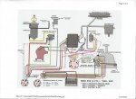
I have a Mercury Thunderbolt 850, serial 4368740. I find the white wire connected to the rectifier on the same terminal as the red wire. The diagram i have shows the white wire should connect to the switch box somewhere. The engine runs but the gauges and ignition are hot all the time. I'm not sure where the white wire from the key switch should go. It doesn't make sense how the switch box gets power like it is wired now. my switch box has maybe a dozen terminals on it and the diagram i have only shows 7, with the white wire going to one of them. Anyone have any ideas?
 

Texasmark

Supreme Mariner
Joined
Dec 20, 2005
Messages
14,636
Only thing hot with the key off would be the power trim if you have it. Everything else should be routed through the ignition switch ON position unless it has a separate dedicated switch, like the function switches on your dashboard. The reason for that is your battery will run down if everything isn't shut off when you turn the key off.

On where the white wire goes, go to the other end. Look for where a component has a white wire attached and ohm it back to the one in question. On any used product there is no telling who or what has been into doing who knows what all to the thing. It's a crap shoot.
 

wrench 3

Commander
Joined
Aug 12, 2012
Messages
2,108
According to my wiring diagrams the white wire shouldn't continue into the engine wiring harness. It comes from the control box and terminates at the harness connector at the engine. It also makes sense with your problem since it shows the white wire going to the "ignition" terminal on the key switch.
I show 13 terminals on the switch box plus 4 grounds. It gets its power directly from the stator. The key switch controls it via the orange wire to ground.
 
Last edited:

Tommy McMinn

Cadet
Joined
Oct 23, 2015
Messages
6
No Title

Thanks for the replies. I agree TexasMark nothing should be hot with the key off. According to the diagram I have, key position A to F is the run Position. Problem is that A to F is connected together at the rectifier essentially the same as having the key in run position all the time. I do not see where the white wire, "F", should go other than it is shown to go to the switchbox but doesn't indicate the proper terminal on the switchbox. My switchbox has 13 terminals as well none marked "white" that i can see. I attached the diagram I have and drew in how mine is actually wired. I supposed I could wire it to a separate switch on the dash but would rather have it correct.
 

Attachments

  • photo238460.jpg
    photo238460.jpg
    66 KB · Views: 10

merc850

Commander
Joined
Jul 7, 2010
Messages
2,039
I think you have a 1976 ADI 850 if so here's the wiring diagram
ADI-850.jpg
 

Chris1956

Supreme Mariner
Joined
Mar 25, 2004
Messages
27,651
Yes, make sure you have the correct wiring diaghram. The 4 coil ignition is ADI and does not have a distributor. Normally the white wire would terminate on the switchbox for distributor ignitions. It would be unconnected on the motor for ADI ignitions.
 

wrench 3

Commander
Joined
Aug 12, 2012
Messages
2,108
My diagram is basically the same as merc850's. The white wire shouldn't be there. I'd tape it up good and tie it back to the harness. Then see how things work.
 

Tommy McMinn

Cadet
Joined
Oct 23, 2015
Messages
6
thanks so much gentlemen. I really appreciate the diagram merc850. I had the epiphany last night, why not just tape it off. It was serving no purpose as it was. Haven't tried it yet, but thats what i will do.
 

Chris1956

Supreme Mariner
Joined
Mar 25, 2004
Messages
27,651
Merc made a transition between battery powered distributor ignitions and ADI ignitions, in the mid to late 70's depending on motor model. The IL6s were last, the IL4s went before. Distributor ignitions needed +12VDC (white wire) to operate. ADI ignitions needed a grounded wire(orange or salmon) to kill the ignition.

Aftermarket motor wiring harnesses were for both types of ignitions and had both the orange(or salmon) wire and the white wire, although one of those was unused, depending on the type of ignition.
 

JamesDunn

Recruit
Joined
Aug 17, 2020
Messages
5
I need wiring diagram For 1976 mercury 850 trim pump. Every diagram I see has a black blue and green wire coming off of the plug on the pump. I have a red black and blue coming off the plug in the front of the pump in the same wires coming out of the back of the pump and I don’t have a clue.
 
Status
Not open for further replies.
Top