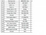
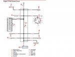
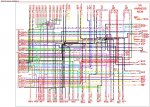
I am a skilled auto mechanic helping a friend diagnose a potentially bad ECM. We've pulled all of the available schematics and it is not apparent to me which line provides 12V to the ECM as it is not identified as such on the schematics. Makes me feel stupid that I can't determine such a basic thing , even with the schematics but......
We obviously want to do some basic testing before condemning the ECM ($$$). The engine stopped suddenly. Now when the ignition switch is turned on, the nothing responds (i.e. no fuel pump) Fuel pump does operate when the relay is energized manually.
Grounds have been verified at the ECM. Can someone describe the basic power connection to the ECM? Pin #, wire color, which of the 2 ECM connectors (A or B) etc. My assumption is the wake circuit purple wire should be battery voltage when ignition is on but I am not sure if the wake circuit tells the computer to turn on or if the wake circuit is controlled on by the ECM when it is powered. (this is a little different strategy than the automotive circuits I am familiar with).
Appreciate the basic direction.


