Mercruiser 3.0 est distributor problem

Timhawk

Cadet
Joined
Feb 21, 2021
Messages
9
Hi all, i have a mercruiser 3.0 2006, bought this boat like this so not sure of its history.
I cant get the timing to advance, i replaced the distributor module with no joy. What i find strange is the rotor arm is pointing to number 4 on the dizzy cap when aligned up on the harmonic balancer. If i turn the dizzy 180 degrees to point at number one which i think is correct it wont start and back fires? Has me lost tbh. Any help would be very much appreciated. Thanks in advance.
 

alldodge

Moderator
Staff member
Joined
Mar 8, 2009
Messages
42,627
If it back fires then it may be 180* out, or needs to be just slightly more adjusted. Put a cork or your thumb over #1 plug hole. Bump the motor over until the pressure pushes the cork out. This is #1 cylinder TDC, install the distributor
 

Timhawk

Cadet
Joined
Feb 21, 2021
Messages
9
Hi, number one cylinder is at tdc and rotor arm pointing at one on the cap. Im baffled
 

alldodge

Moderator
Staff member
Joined
Mar 8, 2009
Messages
42,627
Hi, number one cylinder is at tdc and rotor arm pointing at one on the cap. Im baffled

It might be pointing at #1 but not knowing where the cam is at, it could actually be at #4

If its backfiring and turning the distributor a slight bit in either direction does not make it stop and start running, then most likely its 180* out

My previous comment is to make sure its actually on #1 TDC

Edit: also check firing order 1-3-4-2
 

Timhawk

Cadet
Joined
Feb 21, 2021
Messages
9
Thanks, if i turn the distributor 180 it starts and runs fine, when i align the harmonic balancer and take off the dizzy cap its pointing at 4, my firing order is 1342, when it's set up like this my timing wont advance, also if connect the shift interrupt switch wires to put it in base timing it will stall and wont start again until i disconnect them, something definitely doesn't appear to be right.
 

alldodge

Moderator
Staff member
Joined
Mar 8, 2009
Messages
42,627
The balancer mark comes up on #1 and #4 with a 4 cycle motor. Shutting the motor down and rotate until the mark shows up, is just a 50/50 shot as to which one comes up.

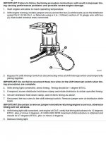
Are you jumping the 2 white wires together on the shunt?
 

Attachments

  • EST Timing.jpg
    EST Timing.jpg
    120.7 KB · Views: 26

Timhawk

Cadet
Joined
Feb 21, 2021
Messages
9
Ahhhh, that makes sense now, ive connected the two white wires on the distributor, it doesnt slow the idle etc, also when i disconnect the shift interrupt switch and join the engine side of the harness together it stalls and wont start? Should i be doing this procedure in neutral or in gear? Thanks for your help its very much appreciated
 

alldodge

Moderator
Staff member
Joined
Mar 8, 2009
Messages
42,627
Would be in neutral
If its stalling with the wires connected then there is something wrong with the distributor module
 

alldodge

Moderator
Staff member
Joined
Mar 8, 2009
Messages
42,627
test
 

Attachments

  • Bul Delco EST and troubleshooting.pdf
    72.5 KB · Views: 12

Timhawk

Cadet
Joined
Feb 21, 2021
Messages
9
Ive managed to get it running sweet and timed 2° atdc which it states on the flame arrestor. Thats with the white wires on the distributor joined together, my problem is when i bypass the shift interrupt switch the engine stalls and wont start until i connect them again. Also no matter what revs it is at or in or out of gear my timing stays at 2° atdc. Thanks again
 

alldodge

Moderator
Staff member
Joined
Mar 8, 2009
Messages
42,627
It shouldn't do that, and I would say the issue is with the module
The timing should advance to about 12* when the jumper is removed as it states in the docs above
 

Timhawk

Cadet
Joined
Feb 21, 2021
Messages
9
Hi, I replaced the module and it is still doing the same. Engine is stalling when shift interrupt bypassed, when i put the engine to 3000 revs the timing retards about 6 degrees.
 

alldodge

Moderator
Staff member
Joined
Mar 8, 2009
Messages
42,627
Something isn't wired right or things are not being done by the spec. Doing the timing procedure must be done step by step

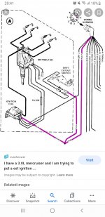
When the shift interrupter is connected together, this should put 12V on the wire feeding the right connector on the module.

Is there 12V on one of the wires going to the shift switch?

Bypass the shift switch. Disconnect the plug from the right connector on distributor and check there is 12V at the pin going to the distributor with key ON?

With the 2 short wires connected together on distributor, is there continuity between them at the connector?
 

Timhawk

Cadet
Joined
Feb 21, 2021
Messages
9
Thank you for getting back, im definitely following the procedure correctly, i have 12 volts at the interrupt switch and 12 volts at the pin. I haven't checked for continuity at the short white wires yet, i have a spare wiring harness and used the plug from it and made a bypass plug and ran it straight to the battery, it stalls that way also.
 

alldodge

Moderator
Staff member
Joined
Mar 8, 2009
Messages
42,627
Connect meter probe to the purple wire (coil would be best) and with motor running should see around 14V.

Connect jumper on short white leads of distributor and see if voltage changes.

With meter still reading voltage jump the switch leads

Did the voltage change?
 
Last edited:
Top