Magneto Wiring Question

dcygan

Cadet
Joined
Sep 26, 2017
Messages
27
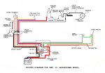
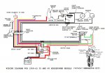
I recently bought two old Johnson 35 HP Seahorse outboards, one is a 1958 with electric start and remote controlled using a wiring harness (RDEL-19), and the other is a 1957 pull start that doesn't use a wiring harness. The '57 motor (RDL-19) was used in fresh water and is in much better condition and therefore I am rebuilding that one, but converting it to electric start with remote controls & wiring harness. The '58 motor with the electric start has only one black wire coming through the bottom of the magneto plate, which connects to the cutout switch and then to the "M" terminal on the ignition switch. However, the '57 pull start motor has 2 black wires coming through the bottom of the magneto plat, one going directly to the cutout switch and the other going to a kill switch that then connects to the cutout switch. My questions are:

1) I swapped out the bottom shroud plate so the engine I'm rebuilding has the correct plate with the wiring plug cast into it and therefore doesn't have a kill switch on the motor, do I completely remove the kill switch and all of its wiring and leave it at that or do I need to run a new black wire from the points/magneto plate to the cutoff switch? and
2) How do both sets of points / coils get connected to the ignition system when the '58 motor only has one black wire going into the magneto plate? Shouldn't it have two wires, one for each set of points / coils. That's how the wiring diagram shows it so I'm confused and need some clarification.

Any insight will be greatly appreciated.

Thanks,
Doug
 

F_R

Supreme Mariner
Joined
Jul 7, 2006
Messages
28,226
You or somebody else seems to have things mixed up. 1957 models had no kill/stop switch, and have only one wire coming from mag. 1958 electric start motors have an ignition key switch, and two wires from the mag. Wired accordingly.
 

oldboat1

Fleet Admiral
Joined
Apr 3, 2002
Messages
9,612
There may be a couple of unused wires connected to the motor side of the plug (used for the optional generator.)
 

dcygan

Cadet
Joined
Sep 26, 2017
Messages
27
Thank you for the responses. Unfortunately, this is my first rebuild of an outboard engine and so I am very unfamiliar with them, but learning a lot as I go. It appears that both engines have been worked on with their power heads removed at some point in their life, hence different fasteners used in a few locations. I double checked and what I mentioned for the wiring for the magneto plate is how they are. It's possible that someone swapped parts a long time ago. Because of your comment F_R I did a little more searching and found a diagram the shows how they are supposed to be wired with a kill switch. None of the other diagrams show a kill switch. If necessary, I will swap out the mag plate. The other problem that I have is the wiring harness that came with the electric start motor is from an Envinrude and using an ohm meter the connections to the motor don't match any of the wiring diagrams that I have. I may have to rewire the engine so that the terminals correctly match where they are supposed to connect to, i.e. starter solenoid, ignition switch, etc.
 

F_R

Supreme Mariner
Joined
Jul 7, 2006
Messages
28,226
No Title

Don't know what diagrams you have, but here is the way they are supposed to be.
 

Attachments

  • photo139250.jpg
    photo139250.jpg
    108.4 KB · Views: 9
  • photo223679.jpg
    photo223679.jpg
    147.8 KB · Views: 6

dcygan

Cadet
Joined
Sep 26, 2017
Messages
27
Thank you for the wiring diagrams. The first diagram only shows an ignition connection for the lower cylinder and nothing for the upper cylinder, why is that? The upper needs to be connected to the ignition system.
 

F_R

Supreme Mariner
Joined
Jul 7, 2006
Messages
28,226
The two sections operate completely independent from each other and without any outside power. The lower one has a wire going to the vacuum cut-out switch, only so the cutout can ground and disable that one cylinder in case of over revving. Since there is no kill switch, no wire is required from the upper one.
 

dcygan

Cadet
Joined
Sep 26, 2017
Messages
27
Thanks again for the helpful information. Out of curiosity, do you know why the 1958-60 wiring diagram shows two wires going to the ignition switch whereas the 1957 just has one wire going to the starter solenoid? Sorry for all of the questions, I'm just trying to figure this out since both diagrams are completely different, but yet the engines are essentially the same.
 

F_R

Supreme Mariner
Joined
Jul 7, 2006
Messages
28,226
As I attempted to say, the 1958 has an ignition switch to shut the motor off. That requires two wires. The switch electrically connects the two wires together when in the OFF position, shorting the two sets of points together & killing the spark. Without spark, the motor stops running. The only way to stop the '57 is to cut the throttle back to so slow that it stalls. OR, choke it and flood it out.

Don't confuse all this with the safety switches which are there for an entirely different purpose.
 
Top