Intermittent Pee Stream 1986 9.9hp J10RCDB.

cprodave

Petty Officer 1st Class
Joined
Jul 1, 2012
Messages
301
I installed a new Water Pump kit back in April and (as an aside?) 20 PSI Pressure Test of lower unit produced no soap bubbles (i.e. Fail). When I run this motor in a water tank with water level at least 6inches above the Water Intake the Telltale usually produces no stream (this is the current condition) . In the past when I ran the motor with Flushing Muffs it has given intermittent Telltale stream--sometimes it pees with the Flushing Muffs after getting to High RPM's, sometimes it doesn't (again this is current condition--even at high RPM's, in-gear to get around the Neutral RPM's interlock).
I stuck a weedwacker string up the Telltale, it didn't really feel like any obstruction was there.

Next step I'm assuming is to run motor on the boat (thinking forward motion of the boat pushes water into the Water Intake better than my Flushing Muffs does) but I am concerned about Overheating. What signs of Overheating should I look for? Also, is it possible for the Thermostat to create a condition whereby the Engine Block is cooled properly but the Telltale doesn't pee properly? Or only if the Telltale is obstructed can you have adequate Engine Block cooling with no Telltale? I wouldn't be surprised if this engine never had a Thermostat change--I have owned it about 3 years. I am not looking forward to changing the Thermostat--lots of disassembly required (correct?) and the bolts look quite rusted...
Stated another way, without risking severe Overheat, how do I know if a new Thermostat is needed? I recall there used to be "Melt Sticks" (not sure what they were called) that you held against the Engine Block, if the stick melted you were headed for an Overheat...
 

cprodave

Petty Officer 1st Class
Joined
Jul 1, 2012
Messages
301
Racerone, thanks for the reminder. I retested in the Tank today but due to the configuration of my tank vs. Engine Stand I can only get water level in the tank to about 6 1/2 inches (i.e. not a full 8 inches--or more) above the top of the Impeller (not top of Water Intake). I am headed to a river tomorrow where I can get a full submersion of the Midsection to at least 8 inches (I made a Sharpie mark on the Midsection. If the on-the-water test tomorrow is successful then I will be puzzled as to why Flushing Muffs do not result in positive Pee Indicator. If the on-the-water test fails then I will disassemble the Water Pump and look for Root Cause.
On this Model/design is it possible to have a good Water Pump but a Failed Thermostat which causes the Pee Indicator to Fail (and of course possibility of Overheat)? Or if the Water Pump is good, but the Thermostat is Failed (stuck) will there still always be flow out of the Indicator (as long as Indicator hose etc is not clogged)?
 

racerone

Supreme Mariner
Joined
Dec 28, 2013
Messages
36,287
Thermostat has nothing to do with the " pee indicator " ----And the " pee water " likely does not go through the engine either.
 

Crosbyman

Vice Admiral
Joined
Nov 5, 2006
Messages
5,006
I just did a 9.9 a few weeks ago....the pee hole was clogged near the exit and was easy to clean up. I did take the opportunity the change the whole pump kit....

easy job. kit a bit pricy but owner happy.
 

cprodave

Petty Officer 1st Class
Joined
Jul 1, 2012
Messages
301
I just did a 9.9 a few weeks ago....the pee hole was clogged near the exit and was easy to clean up. I did take the opportunity the change the whole pump kit....

easy job. kit a bit pricy but owner happy.
Last weekend I retested the motor mounted on my 12 foot Higbee Sneakbox and noticed that this boat has a relatively high Transom. Therefore on the boat I am not getting even 6 inches of water above the Impeller. i.e. insufficient hydrostatic head according to the 6-8inch rule. So testing in deeper water (greater submersion than I can get on this boat) is required.

Therefore I removed the Lower Unit, marked the Drive Shaft with masking tape 8inches and 10 inches above the TOP (not the Bottom and not the mid-height) of the Impeller. Stated differently, the masking tape was 5 inches and 3 inches (respectively) below the top of the Drive Shaft. Then I put the Drive Shaft into my DeWalt DCD771 Cordless Drill spun at highest speed (1500 RPM or less according to DeWAlt website) with the Lower Unit Submerged in a deeper water tank than I have been using previously. I got no flow at 8 inches submersion. I found that at least 10inches of water were required to get any flow at all out of the Water Pump. And I wouldn't call it a strong flow--possibly not enough to get up to/through the Powerhead.

Then I disassembled the water pump and found everything assembled correctly according to the OMC diagram. The Impeller has no damage (it has about 10minutes runtime on it) although it makes a squeaking sound when Drive Shaft is turned by hand.

I am thinking there is something obstructing water path into the pump thereby requiring higher than normal (6 to 8 inch) submersion. Also it seems noteworthy that on the assembled motor with Flushing Muffs and garden hose I don't get any flow out of the Telltale. However when I attach the Flushing Muffs and Garden Hose to the disassembled Lower Unit and spin with cordless drill I do get water flow out of the Water Pump but similar to Tank Test the water flow seems weak.

In a separate update I will attach a couple photos with questions about the condition of my Water Intakes.
 

cprodave

Petty Officer 1st Class
Joined
Jul 1, 2012
Messages
301
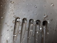
For the water intakes (below the Cavitation Plate) are the 5 holes supposed to have plastic screen? On my motor both starboard and port side the plastic screen does not exist on the lowest (5th) hole. On the starboard side the topmost screen is partially clogged. On the port side the topmost screen is partially clogged and the 4th screen is missing.
 

Attachments

  • 20201030_110453.jpg
    20201030_110453.jpg
    2.3 MB · Views: 3

cprodave

Petty Officer 1st Class
Joined
Jul 1, 2012
Messages
301
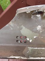
For the water intakes (below the Cavitation Plate) are the 5 holes supposed to have plastic screen? On my motor both starboard and port side the plastic screen does not exist on the lowest (5th) hole. On the starboard side the topmost screen is partially clogged. On the port side the topmost screen is partially clogged and the 4th screen is missing.
Above the cavitation plate and anode there are 6 holes each on starboard and port sides. 4 holes are throughholes while 2 holes are blind holes i.e. not all the way through. Is this correct configuration? It appears that even if the 2 blind holes were drilled to become throughholes there would be no increase in water available to the water pump.
 

Attachments

  • 20201030_110722.jpg
    20201030_110722.jpg
    1.4 MB · Views: 0

racerone

Supreme Mariner
Joined
Dec 28, 2013
Messages
36,287
Those 6 holes have nothing to do with flow to the pump.-----Yes usually the bottom hole is not covered by a screen.-----In my opinion these pumps are elegantly simple.----Hard to put one together with proper parts and it not work as a result of that work !
 
Top