Help installing a voltmeter

nearpar

Petty Officer 2nd Class
Joined
Sep 4, 2010
Messages
143
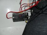
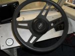
I have a 17ft Sea Nymph with a Mercury outboard I purchased the boat and it needed to be rewired. I made a new dash out of aluminum and gutted 90% of the wiring. Everything is going well I soldered and shirked wrapped all connections and installed a new Electrical panel in the boat. I also installed a Nice voltmeter in the dash, but I am not sure how I should wire this ? Should I run it direct to the hot side of the Distribution panel with a fuse, and switch it on when I need it ? This boat is equipped with and outboard motor the ignition switch is located in the throttle assembly. I think it would be difficult to try to switch it on and off with the key... :)Panel 1.jpgPanel 2.jpg
 

bruceb58

Supreme Mariner
Joined
Mar 5, 2006
Messages
30,537
Re: Help installing a voltmeter

Switching it on/off with the key is the correct way to do it.
 

Silvertip

Supreme Mariner
Joined
Sep 22, 2003
Messages
28,771
Re: Help installing a voltmeter

If you have any other gauges in this boat, they already operate from the ignition switch. Just wire the POS, NEG, and LIGHT terminals to the same terminals on any other gauge. You do not want or need a separate switch for the voltmeter with the above scheme. There are also POS and NEG terminations in the engine harness in the area of the throttle/shift control box. If the ignition switch is on the dash you connect the POS wire to the gauge to the "I" terminal on the ignition switch (I/O's) or to the "A" terminal if this is an outboard powered boat. I hope you plan to dress up that wiring a bit. It is not supported well enough. I also see red wires from the panel spliced into much larger wires. Can't make out the fuse ratings but the fuse must never have a higher rating than the wire in that circuit.
 

nearpar

Petty Officer 2nd Class
Joined
Sep 4, 2010
Messages
143
Re: Help installing a voltmeter

The picture is a little deceiving this is mounted under the dash in the upper right hand corner and is supported by 4- 1/8 stainless nuts and bolts with lock washers. The two splices that you are seeing are one gauge difference 16 at the terminal and 14 the rest of the way I will change that so it is 14 at the block as well. The splices are soldered and shrink wrapped. There is only one gauge in the boat and that is the volt meter mounted in the dash. There will not be anymore. The ignition switch is mounted in the throttle/Shift control box on the side. I am still working on this project so it is not done yet please let me know what you mean by " not supported enough " as any help is invited.

Thank you
 

bruceb58

Supreme Mariner
Joined
Mar 5, 2006
Messages
30,537
Re: Help installing a voltmeter

Depending on how much current you are drawing, that short length of 16 gauge wire may be fine. Not a very good practice though.
 
Joined
Feb 17, 2012
Messages
2,906
Re: Help installing a voltmeter

not supported means the wires are able to bounce around and that puts stress on the push on connectors that over time loosen then you start to get glitch's. If you add tie wraps when you are done then the force of the wires bouncing is shared over lots of connections and other parts that you tie wrap to and this reduces problems.
 
Top