Fuel sending unit - testing / troubleshooting

kdiddle

Petty Officer 2nd Class
Joined
Mar 22, 2018
Messages
147
Throwing this out here - as I'm at my wits end as to what's going on.

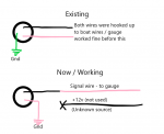
Background - my fuel gauge on my 16yr old boat didn't work on our first outing this year. In order to test my gauge, I grounded the pink wire which pegged my fuel gauge. I understood that to mean that I had a faulty sending unit. I ordered an identical replacement, and after hooking it up - it doesn't work either.

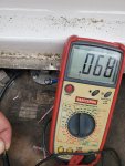
Of course - I only thought to test the resistance AFTER having it installed, but I got the following reading on the sending unit which, according to the manufacturer, is an accurate ohm reading for approx 3/4 tank (which is accurate). However, my gauge is still not working, but will peg out when I ground the pink wire. Apparently .068 must represent 68ohms here...

How is it that I'm getting movement from my gauge when I ground, but not when hooked up to the sending unit?
 

Attachments

  • photo328672.jpg
    photo328672.jpg
    1.6 MB · Views: 0

kdiddle

Petty Officer 2nd Class
Joined
Mar 22, 2018
Messages
147
I think I should mention that my sending unit is the vertical tube types, which means it has two wires going into the unit, one +12V the other being the pink sending wire. There is also a ground on one of the mounting screws...I also direct connected a ground to the unit just to make sure I have a good ground - no change whatsoever.
 

dingbat

Supreme Mariner
Joined
Nov 20, 2001
Messages
16,313
First off, it would help if you put the meter on 200 ohms instead of 2,000 ohms ;) Can't read 240 but you would be reading actual

Sounds like you have a bad wire somewhere between the sender and the gauge.
Run a wire from the sending unit directly to the gauge to confirm
 

kdiddle

Petty Officer 2nd Class
Joined
Mar 22, 2018
Messages
147
yeah, I wondered about the setting too, but the instructions on the KUS website specifically said to put setting on 2k for some odd reason...

Well, I'm 100% certain I'm getting 12v on the black wire, and grounding the pink wire pegs the gauge as it should...do you think the pink wire might be compromised somehow? To eliminate that possibility I suppose run a separate wire from pink on unit directly to the back of my gauge then?
 

Scott Danforth

Grumpy Vintage Moderator still playing with boats
Staff member
Joined
Jul 23, 2011
Messages
50,234
I think I should mention that my sending unit is the vertical tube types, which means it has two wires going into the unit, one +12V the other being the pink sending wire. There is also a ground on one of the mounting screws...I also direct connected a ground to the unit just to make sure I have a good ground - no change whatsoever.

you should have ground and signal coming to the sending unit. it is a variable resistor to ground. if you have 12 volts going to the sending unit, not only will you fry something, you may blow up in the process
 

kdiddle

Petty Officer 2nd Class
Joined
Mar 22, 2018
Messages
147
Hey Scott Danforth - I did not do any wiring mod here, simply pulled out the old and replaced sending unit. I verified the KUS troubleshooting guide confirms that the black wire should be 12v and the pink wire is the sending unit wire that goes to the gauge. See screenshot:
 

Attachments

  • photo328674.jpg
    photo328674.jpg
    61.5 KB · Views: 2

alldodge

Moderator
Staff member
Joined
Mar 8, 2009
Messages
42,548
Three wires on the sender - light bulb
You have a Centroid or Moeller sending unit and testing is not done the same as the regular fuel gauge. Also the gauge is not compatible with a regular sender

Who makes your sender?
 

kdiddle

Petty Officer 2nd Class
Joined
Mar 22, 2018
Messages
147
so I just spent 20 mins on the phone with KUS support. Apparently the black wire should be 12v and coming from the gauge, and the pink wire is supposed to go directly to ground (my sending unit also has a green ground going to the mounting bolt for some reason).

I'm absolutely confused as (1) I haven't changed any wiring and this gauge worked great before hooked up this way and (2) I'm pretty certain the pink wire does go to the back of the gauge (which doesn't sound like a ground to me)
 

kdiddle

Petty Officer 2nd Class
Joined
Mar 22, 2018
Messages
147
My gauge is made by Faria, and as I mentioned, I haven't removed/changed any hookups on the back of the gauge yet, but I suppose my next step is to remove it and see how its hooked up...
 

kdiddle

Petty Officer 2nd Class
Joined
Mar 22, 2018
Messages
147
AllDodge - my sending unit is only two wire (black/pink). The 'third' wire is just a ground wire that clips to one of the mounting bolts...according to support Black = +12v and Pink = ground.
 

alldodge

Moderator
Staff member
Joined
Mar 8, 2009
Messages
42,548
which means it has two wires going into the unit, one +12V the other being the pink sending wire

AllDodge - my sending unit is only two wire (black/pink). The 'third' wire is just a ground wire that clips to one of the mounting bolts...according to support Black = +12v and Pink = ground.

Still sounds like 3 wires, but ok its a 2 wire sender. The grounds should read zero ohms (or real close to zero) back to the battery negative

Your float has reed switches, so with it connected to the gauge, you should be able to move it up and watch gauge move to full. Should also be able to put meter on ohms and watch the resistance step up as float goes up
 

Scott Danforth

Grumpy Vintage Moderator still playing with boats
Staff member
Joined
Jul 23, 2011
Messages
50,234
your fuel sender is a variable to ground per the data sheet.

KUS.jpg

Black is ground
pink is signal - 240 ohms at empty, 33 ohms at full

The wire colors are not only an SAE standard, they are an ISO and ABYC standard

wire it like that, then check.
 

kdiddle

Petty Officer 2nd Class
Joined
Mar 22, 2018
Messages
147
Well, I'm pretty sure I just killed some brain cells in this process, and I still can't make heads nor tails of what's going on. I'll attach a pic for reference, but after making approx 5 calls to KUS support where they assured me the black was 12v and the pink was absolutely common ground...they finally clarified that wiring scheme was only for their gauges.

Apparently my Faria is wired differently. I have +12v ignition wire on the back of the gauge (purple) a ground (black) and a signal wire (pink) which i verified via voltmeter is the same pink at the sending unit.

After following their instructions (to no avail)...I hooked up the black wire from the sending unit, to the pink signal wire going to the gauge. THEN after grounding the pink wire from the sending unit, the gauge is working perfectly.

What makes absolutely no freaking sense is that I now have left the +12v black wire (that 100% was hooked up before when it was working) completely disconnected. I mean, I guess it doesn't matter as long as its working, but holy crap this is melting my brain...see attached if this makes no sense to you...
 

Attachments

  • photo328692.png
    photo328692.png
    32.6 KB · Views: 1

alldodge

Moderator
Staff member
Joined
Mar 8, 2009
Messages
42,548
Some manufactures are just weird
The tank should have a ground wire on it to keep static electricity from building up. Connect the boat black wire back to one of the sender lugs
 

kdiddle

Petty Officer 2nd Class
Joined
Mar 22, 2018
Messages
147
yeah they told me to disconnect the green ground wire as part of the troubleshooting. I'll hook the ground wire back to one of the mounting bolts...thanks for the input all. I'm just glad its working, despite the fact it makes no damn sense...
 

dingbat

Supreme Mariner
Joined
Nov 20, 2001
Messages
16,313
What makes absolutely no freaking sense is that I now have left the +12v black wire (that 100% was hooked up before when it was working) completely disconnected. I mean, I guess it doesn't matter as long as its working, but holy crap this is melting my brain...see attached if this makes no sense to you...
A ground is a ground.....the circuit is being grounded through the gauge to ground.

As noted above, the ground on the tank is to dissipate for static. Need to connect the ground from the tank into the circuit as well.
 

kdiddle

Petty Officer 2nd Class
Joined
Mar 22, 2018
Messages
147
So then since the pink wire needs to go to ground, I suppose I'm going to run a fresh ground wire to my battery just to ensure its got a good connection (and its nearby), and I'll just tie that ground into the mounting flange before connecting to the sending unit. That way both are well grounded...
 

Scott Danforth

Grumpy Vintage Moderator still playing with boats
Staff member
Joined
Jul 23, 2011
Messages
50,234
the way your Faria gauge works..... 12 volts is on the I terminal (purple wire), the black wire is ground, this goes to the gauge "Ground" terminal and the "S" terminal is your sender. for fuel, this has been pink for about 65 years

the Air-core motor inside the gauge uses a resistor bridge to move the gauge. part of that bridge is the sender resistance

you vary the S terminal to ground with the sender

the way the sender works for a faria gauge (and a VeeThree and VDO and COBO, etc) is one wire goes to ground, not the bonding, however to battery ground. the other wire is pink and that goes to the gauge "S" terinal

wire the black wire from the sending unit to your ground bus
wire the pink wire from the sending unit to your S terminal on the gauge
 
Top