Frank Acampora
Supreme Mariner
- Joined
- Jan 19, 2007
- Messages
- 12,004
This post is for those people who have no idea what is inside their Force engine. I have posted a couple of photos that I happen to have on hand. I invite others to post more photos to add to the collection.
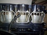
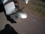
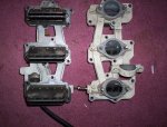
The first photo is a three cylinder Force engine, veiwing from the open bypass side. This one happens to be a mid 90s 85 HP needing a rebuild. Four cylinder engines are the same mid leg and lower unit with one more cylinder added to the block. That is why the four cylinder engines only weigh about 25 pounds more than the three cylinder engines.
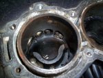
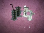
The second is showing the piston at bottom dead center with the exhaust ports open. Look closely at the bottom of the cylinder and you will be able to see a bypass port. Look at the top portion of the photo, exhaust side of the piston, and you will see why this engine is apart for rebuilding.
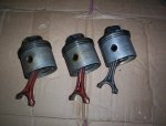
The third photo is of the pistons (generic) These happen to be from an older three ring engine. Newer ones have two rings each.
The fourth photo shows the Big ends of the piston rods connected to the crankshaft. Note the rollers in the uncapped rod.
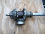
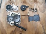
Fifth photo shows a gear pak from an older two piece lower unit. Newer lower unit gear paks are similar with a few changes in how the reverse gear is carried and a longer prop shaft. While gears are cut differently, the drive dog clutch and method of engagement is the same.
Now: the two cycle engine operates by inducting fuel and air through a reed valve into the crankcase where the crankshaft is. This is accomplished by the bottom of the piston as it moves up to top dead center. As the piston moves down, it makes the volume of the crankcase smaller and the air/fuel is pumped through the bypass up into the cylinder. the piston again moves up and compresses the mixture and it is ignited by the sparkplug. This sequence happens once for each piston every revolution of the crankshaft.
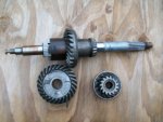
The rotation of the crankshaft is transmitted to the lower unit pinion, here shown at the bottom of the photo, by the driveshaft. The pinion is constantly engaged with both the forward gear and reverse gear so both are constantly turning. When the drive dog clutch, here pushed backward into reverse by the thin shaft on the left, is pushed into one gear, that gear turns the clutch which you can see is splined to the prop shaft. The drive dog clutch turns the prop shaft. On the left side of the photo, forward gear is carried in a relatively massive tapered roller bearing. The prop shaft drive dog splines bear on the forward gear and thrust loads are absorbed by the roller bearing.
The first photo is a three cylinder Force engine, veiwing from the open bypass side. This one happens to be a mid 90s 85 HP needing a rebuild. Four cylinder engines are the same mid leg and lower unit with one more cylinder added to the block. That is why the four cylinder engines only weigh about 25 pounds more than the three cylinder engines.
The second is showing the piston at bottom dead center with the exhaust ports open. Look closely at the bottom of the cylinder and you will be able to see a bypass port. Look at the top portion of the photo, exhaust side of the piston, and you will see why this engine is apart for rebuilding.
The third photo is of the pistons (generic) These happen to be from an older three ring engine. Newer ones have two rings each.
The fourth photo shows the Big ends of the piston rods connected to the crankshaft. Note the rollers in the uncapped rod.
Fifth photo shows a gear pak from an older two piece lower unit. Newer lower unit gear paks are similar with a few changes in how the reverse gear is carried and a longer prop shaft. While gears are cut differently, the drive dog clutch and method of engagement is the same.
Now: the two cycle engine operates by inducting fuel and air through a reed valve into the crankcase where the crankshaft is. This is accomplished by the bottom of the piston as it moves up to top dead center. As the piston moves down, it makes the volume of the crankcase smaller and the air/fuel is pumped through the bypass up into the cylinder. the piston again moves up and compresses the mixture and it is ignited by the sparkplug. This sequence happens once for each piston every revolution of the crankshaft.
The rotation of the crankshaft is transmitted to the lower unit pinion, here shown at the bottom of the photo, by the driveshaft. The pinion is constantly engaged with both the forward gear and reverse gear so both are constantly turning. When the drive dog clutch, here pushed backward into reverse by the thin shaft on the left, is pushed into one gear, that gear turns the clutch which you can see is splined to the prop shaft. The drive dog clutch turns the prop shaft. On the left side of the photo, forward gear is carried in a relatively massive tapered roller bearing. The prop shaft drive dog splines bear on the forward gear and thrust loads are absorbed by the roller bearing.