Hi Guys,
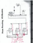
I have a 1987 175hp Evinrude V6 outboard. I have attached a diagram that I was finally able to find after buying a factory service repair manual.
1. As marked on the diagram under the carbs there are check valves. These valves all flow in outward direction. I have cleaned all of these, last season these were clogged with a lot of oil. My question is if all of these check valves flow in an outward position what is the purpose of them being tied together?
2. I removed a fuel primer hose line while the engine was running. Gas was coming out like a fire hose it shot across the boat, is that normal? Or does the primer solenoid need to be replaced.
3. The VRO pump was removed, does anyone know what the proper Fuel / Oil mixture is?
Thanks,
Any help or comments are greatly appreciated.


