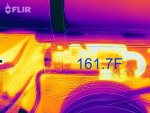
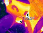
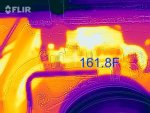
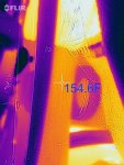
I think you've read this before Ted but if not then below is just a copy and paste of what will show up... But for better images, etc. search online ( Troubleshooting Teleflex Water Temperature Gauges) under james town marine.
PS, The digital type sending unit the scan tool reads has always been very accurate vs what most analog gauges read on all models with either style cooling system.
Water Temperature System Accuracy?
Temperature systems used on boats and other vehicles give a general indication of the temperature in which the sender is operating. We use the term "general" as the system can vary to a maximum 15 degrees from actual temperature.
The gauge itself is accurate to within about 5 degrees at the mid-scale position. The sender is accurate to within 10 degrees at 200 degrees (as are competitive units). The sender tolerances widen as temperatures become higher or lower than 200 degrees. (cont'd. on next page)
Although sender/gauge tolerances rarely run to the maximums (at the same time), the system can possibly indicate up to 15 degrees difference from actual temperature at 200 degrees. These specifications are developed at a system voltage of 14 volts. The sender is also susceptible to "self heating" when electrical current passes through the sender. The self heating causes the sender to become warmer than the actual temperature of the fluid (the gauge is compensated for this effect at 14 volts). If the system voltage is varied to 13 or 15 volts the gauge may read 5 to 6 degrees higher also.
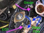
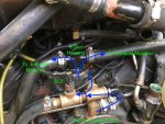
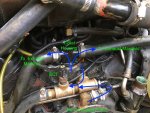
In a few cases it is necessary to put a temperature sender and a temperature switch (to operate a light or buzzer) in the only engine opening. In this case a "tee" is used. However, when the sender (or switch) is moved away from the water flow, the water around the sender bulb tends to run cooler. The gauge will also show a cooler reading than the actual water temperature inside the engine. Use of "extenders" or "tees" is generally not recommended.
Water & Oil Temperature Sender Identification Guide
Use this chart for field identification of Teleflex water temperature senders. (ID code stamped on wrench hex of sender. See illustration at left of chart.)
Water Temperature System (Inboards & Stern Drives)
- To test gauge, voltage from "I" to "G" terminals must be 10-16 VDC. No wire on "S" terminal. Gauge pointer should rest below 120. Next, connect the "S" terminal to the "G" terminal (leave "I" and "G" terminals connected). The gauge pointer should rest above 240.
- The resistance of the sender can be measured to determine the sender's correct operation. Remove wire to gauge. Connect an ohmmeter to terminal of sender and to engine block. Approximate values are: 75 (room temperature) = 600 to 800 ohms; 212 degrees = 55 ohms. (These are single station values- twin station values would be 1/2 these numbers).
- If sender is shorted (0 ohms) gauge will read above 240F.
- If sender has infinite resistance (Open) gauge will read below 120F.
- If the gauge reads lower than expected, was sealer used on the sender threads? (See illustration.)
- The accuracy of the system (gauge, sender, voltage range) can vary as much as 16 degrees at 180F.
- Use of pipe extenders to plumb both a sender and temperature switch (for horn or warning light) from one port is not recommended. The amount of weight extended on the fitting of a vibrating engine could cause fatigue-related breakage. Also, the sender is removed from water flow inside the engine and will probably read cooler.
- Teleflex does not offer senders for metric threaded ports.
- Dual Station installations:
- When replacing one gauge in a two station installation, the second gauge may need to be replaced as well.
- Mixing two gauges from different manufacturers to one sender may cause an error in both gauges.
- If one gauge fails the second gauge will read much higher than expected.
- If sender fails "open", both gauges will read below 120F.
- If sender fails "short", both gauges will read above 240 degrees.
- Twin engines: It may be helpful in troubleshooting to switch either the senders or the gauges from engine to engine.


Water Temperature Monitoring- Outboards
- The temperature monitoring kit includes all parts to adapt to any of the situations noted above. Yamaha engines will require an adapter P/N 61886P in addition to the kit.
- Outboard engines use raw water for cooling and are mostly aluminum, so they operate cooler than stern drives. Consult dealer or engine manual to determine maximum operating temperature of your engine.
- The sender in the kit has 1/8-27 NPT threads with I.D. Code "10" or "60" stamped on the hex. Senders stamped "230" won't work correctly.
- Part number of the sender is 52320S010; the flat bracket is 54552; the Z bracket IA55009.
- Some engines include a threaded hole directly into a water line. The temperature sender can be threaded into the hole, using no sealant on the threads. The threads create the electrical ground.
- Some engines have a blind threaded hole for a temperature sender that does not enter the water jacket. After applying thermal compound to the hole, thread the sender in snugly, again using no sealer.
- Some Mercury engines have a blind hole flanked by two bolts. These are for tightening the flat plate. First place thermal compound in the hole, then drop the aluminum spacer in the hole. Thread sender into bracket over hole until it hits spacer.
- The Z bracket installation is used most often as it fits any engine. The Z bracket through hole is held by any one of the engine's cylinder head bolts. The sender is threaded into the bracket's remaining hole down against the cylinder head. Scrape the paint from the head under the sender to get good thermal transfer.
- The kit is supplied with one sender. If a sender is desired on each cylinder bank on V type outboards, a double pole ON-ON switch must be used to switch sender input to the gauge. The gauge can not accurately handle two senders at one time.
- Testing the gauge for operation: Connect a hot wire to "I" and ground wire to "G". Gauge should read below the C. Next, Short the "S" terminal to "G". The pointer should go above the H. If the pointer sweeps this way, the gauge is fine.
- Testing the sender: At room temperature, with no wires on the sender, it should measure approximately. 600-800 ohms on test meter.
- Replacement outboard sender IA96035 cannot be used with this gauge. The gauge will read very high. IA96035 is only for pre-1995 Johnson/Evinrude engines with a 50-250F gauge.


