Checking power trim sender

maineiac5586

Senior Chief Petty Officer
Joined
Feb 14, 2009
Messages
658
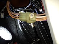
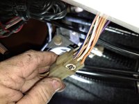
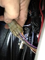
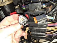
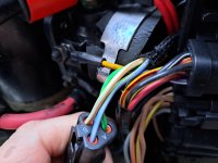
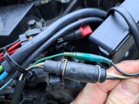
New to me 1997 johnson 115 spl v4 bubbleback. Disconnected triangle connector under the connector panel after removing the cover of the connector panel (under the hood). Ignition key off I put a clamp on the green pin and one on the blue pin. Full down shows 158 Ohms. Meter goes to 1 while motor is moving up or down. I stopped moving the motor about 1/2 way and meter went from 1 to 158 Ohms again. Same ohm reading whether down all the way or trimmed up. Assuming the sender is bad unless someone says otherwise. Not sure which wire to use at the helm to connect to trim guage. Boat doesn't have a guage. Looking to add one . I see a triangle connector up at the helm but it has blue, green and red wires. Not seeing a brown white wire in that connector. I have a 2 wire connector that goes to the binnacle control. Need some help. Inputs welcome
 
Last edited:

maineiac5586

Senior Chief Petty Officer
Joined
Feb 14, 2009
Messages
658
Are you sure you are testing the correct wires ???
Probably not
I found a round connector under the hood with wires from the sender. I think 1 black and one white with brown . How do I test at that connector?
 

Chris1956

Supreme Mariner
Joined
Mar 25, 2004
Messages
27,216
When you put the meter on the blue and green wires, you are likely testing the resistance of the PTT relays. That is why it changes when you apply power to tilt the motor.

On my '98 Johnny, the PTT control wires (green and blue) and the white/brown PTT sensor wires share a connector at the engine. The wiring harness breaks that out, sending the purple (power), black (ground) and the white/brown wires to ring connectors at the dashboard for the PTT gauge.

Check across white/brown and black ground wires for resistance, at various stages of tilt. I would recommend starting at the dashboard and working back, if the readings are bad.
 

dingbat

Supreme Mariner
Joined
Nov 20, 2001
Messages
15,539
If your sending unit is like mine, follow the blue and green wires coming from the trim sender back to the relay.

Disconnect either wire from the relay. Connect meter to either wire and ground. Manually move the trim lever up and down.

I don’t care about the reading as much as the linearity of the output. Any “flat spots” or “jumps” is a sign of a compromised winding in the rheostat.
 

maineiac5586

Senior Chief Petty Officer
Joined
Feb 14, 2009
Messages
658
I looked all under the dash. Not finding the 3 loose wires with ring terminals. I found a white with brown wire in a connector with no wire coming out the other side of the connector in line with the white with brown wire. I put power and ground to the guage and jumpered a wire from that white with brown stripe wire to the sender input of the guage. Guage did not change with up and down movement. Anyone know if that white with brown stripe wire is the sender wire? I have to check for signal back at the motor still.
 

Attachments

  • 20231225_134911.jpg
    20231225_134911.jpg
    4.2 MB · Views: 6
  • 20231225_134917.jpg
    20231225_134917.jpg
    3.7 MB · Views: 6
  • 20231225_134925.jpg
    20231225_134925.jpg
    1.4 MB · Views: 6

maineiac5586

Senior Chief Petty Officer
Joined
Feb 14, 2009
Messages
658
Anybody have an answer as to if the white with brown stripe wire in this harness connector is for trim guage signal?
 

Chris1956

Supreme Mariner
Joined
Mar 25, 2004
Messages
27,216
The wiring diagram from my '98 Johnny shows only one white/brown wire. It is for the trim sender. There are several tan wires with various trace colors.
 

Chris1956

Supreme Mariner
Joined
Mar 25, 2004
Messages
27,216
If you do not have a water pressure gauge, I would recommend removing the trim gauge and adding one in it's place. It is much more useful than a trim gauge.
 

maineiac5586

Senior Chief Petty Officer
Joined
Feb 14, 2009
Messages
658
If you do not have a water pressure gauge, I would recommend removing the trim gauge and adding one in it's place. It is much more useful than a trim gauge.
Can you tell me where to attach the pressure guage on the powerhead?
 

Chris1956

Supreme Mariner
Joined
Mar 25, 2004
Messages
27,216
My Johnny 150HPV6 had a unused brass plug in the water jacket on the head. I removed the plug and added the pressure fitting.

Not sure what your motor has, but there is usually a way to do it. Worse case is to tee into the telltale.

On my old inline six Merc, I removed the telltale fitting on the water jacket and added a brass tee. The tee had a place for the original fitting plus the water pressure fitting.
 

maineiac5586

Senior Chief Petty Officer
Joined
Feb 14, 2009
Messages
658
Working on trim guage again. I disconnected the triangle connector and put a jumper from the white with brown stripe pin to the sender on the guage. I also put power and ground to the guage. The guage is not changing when tilting motor up and down. I also jumped the white with brown stripe wire at the circular connector with no success. Either I'm using the wrong connector or trim sender is n.g.
 

Attachments

  • 20240110_164012.jpg
    20240110_164012.jpg
    3.4 MB · Views: 2
  • 20240110_164032.jpg
    20240110_164032.jpg
    3.6 MB · Views: 2
  • 20240110_164317.jpg
    20240110_164317.jpg
    3.2 MB · Views: 2

dingbat

Supreme Mariner
Joined
Nov 20, 2001
Messages
15,539
Working on trim guage again. I disconnected the triangle connector and put a jumper from the white with brown stripe pin to the sender on the guage. I also put power and ground to the guage. The guage is not changing when tilting motor up and down. I also jumped the white with brown stripe wire at the circular connector with no success. Either I'm using the wrong connector or trim sender is n.g.
Words of wisdom….when troubleshooting electronics you always start at the “source” whether it be power or signal.

Do yourself a favor and follow the wires from the sending unit to connector where they interface to the trim motor on the motor.

Pull the connector apart and check resistance between the two wires coming from the trim sender.

Resistance should change when you actuate the sender arm. If not, you have a bad sending unit
 

maineiac5586

Senior Chief Petty Officer
Joined
Feb 14, 2009
Messages
658
Words of wisdom….when troubleshooting electronics you always start at the “source” whether it be power or signal.

Do yourself a favor and follow the wires from the sending unit to connector where they interface to the trim motor on the motor.

Pull the connector apart and check resistance between the two wires coming from the trim sender.

Resistance should change when you actuate the sender arm. If not, you have a bad sending unit
So that would be at the 2 wire connector?
 

Attachments

  • 20240110_164317.jpg
    20240110_164317.jpg
    3.2 MB · Views: 1

saltchuckmatt

Lieutenant Commander
Joined
Jul 19, 2019
Messages
1,843
Just to throw my input in.....and like what was stated, I rarely use my trim gauge. Not very accurate in terms of water conditions, typically not in my field of vision when cruising (should be looking at the water) and I trim my motor by sound and boat attitude.

One thing to note and not sure what you have, but the sender swivels under the motor and it likes to get gunked up and not rotate which of coarse makes the gauge not move but I'm assuming that's not your case.

Best of luck.
 
Top