


Hello,
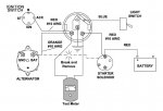
The boat is a 40 y/o 26 ft. Monark with a 165 hp inline 6 Mercruiser that I am rewiring for the fire dept. I volunteer for. In addition to rewiring the boat, I am replacing the gauges and going to a Teleflex kit. Currently the boat has an ammeter but the kit has a voltmeter. I have all the gauges installed and functioning correctly, but I have a question about the alternator output wire (orange wire) that I removed from the ammeter. It isn't used on the voltmeter and I haven't be able to find a wiring diagram that shows what to do with it after it is unhooked from the ammeter. Right now, I have capped and stowed it in the wire harness behind the instrument panel. Can anyone tell me if it must be hooked up in some manner or just leave it unhooked. The engine starts fine and there is about 12.59 VDC output to the start battery, so I am getting "some" charge from the alternator to the battery. I would prefer more output but that's the other question. Although 12.59 VDC is enough to keep the start battery charged, will it be enough to maintain the start and house batteries? I am using a BEP DVSR and a generic battery switch in the system. In the diagram I have uploaded, it shows a wire between the battery post on the alternator and battery post on the start solenoid that is removed when installing an ammeter. Should I now run a wire between those two points since I am going to a voltmeter?
Thanks for any help you might be able to give me.
Rescue31

.jpg")