Alarm circuit wiring Volvo Penta 5.0 GLPEFS

criscolumbus

Cadet
Joined
Jul 8, 2018
Messages
28
Asking for information on my first post......:facepalm: oh well :faint2:

I have dug through the search for a while and the wonderful sticky information but am coming up short on finding the specific alarm wiring.

Best I can tell the alarm gets power from the green wire via the alternator when the engine is running and from the R terminal on the starter when cranking ( I am guessing to give it a test alarm when starting ? )

Apparently the previous owner replaced the starter and the replacement starter does not have the old resistor output terminal so they just left that wire off. If I am correct on the wiring, the only adverse effect is I will not get the test alarm when starting the engine.
 

criscolumbus

Cadet
Joined
Jul 8, 2018
Messages
28
have you looked at the wiring diagrams in the factory manual? http://162.144.28.33/lib/library.html#

Yes I looked it up. Best I can tell the diagram vs the pinout description is 1 number off. but if I assume the PU wire is #6 instead of #5 like it is labeled, it is wired like I thought. Looks like as long as the starter is engaged I should not have power to the ignition coil until the alternator spins up fast enough to have an output. Interesting. It does start ok.
 

criscolumbus

Cadet
Joined
Jul 8, 2018
Messages
28
In studying the diagram quite a while it gets confusing due to the ledged not matching the diagram. (at least the way I see it). Is the I terminal at the starter no longer necessary and was just a carry over from the old points ignition? If so. why does it still have the PU wire going there?
 

Scott Danforth

Grumpy Vintage Moderator still playing with boats
Staff member
Joined
Jul 23, 2011
Messages
49,831
to provide power to the fuel pump while cranking
 

criscolumbus

Cadet
Joined
Jul 8, 2018
Messages
28
to provide power to the fuel pump while cranking

According to the diagram, the fuel pump gets its power via alternator L2 terminal through a diode when engine is running and from the start assist relay though a diode when cranking.

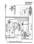
The diagram for this particular model is awful but if you zoom up on it you can trace.

The diagram shows from the engine harness plug a purple wire going to the following: 1) starter R terminal. 2) Ignition coil +. 3) alternator EXC terminal.

This is an electronic pickup ignition so there is no resistor needing a bypass. Having a hard time getting my head wrapped around the need for the connection at the starter.:confused:
 

Bt Doctur

Supreme Mariner
Joined
Aug 29, 2004
Messages
19,315
Personally I would wire in a new feed from the coil. Cant see relying on a alt to power the fuel pump. lose the alt and your dead in the water.
With a new feed you can lose the alt but still have the fuel pump work.
 

criscolumbus

Cadet
Joined
Jul 8, 2018
Messages
28
Personally I would wire in a new feed from the coil. Cant see relying on a alt to power the fuel pump. lose the alt and your dead in the water.
With a new feed you can lose the alt but still have the fuel pump work.

I can understand your reason for powering the fuel pump that way but that has nothing to do with the purple wire that is shown going to the starter. Help me understand why volvo has a connection to the starter R terminal when there is no resistor to bypass in the ignition.
 

criscolumbus

Cadet
Joined
Jul 8, 2018
Messages
28
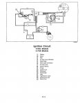
The first two attached pictures show the wire at the starter in question. From the ignition section in the manual it does not show it. :confused:
 

Attachments

  • photo295178.jpg
    photo295178.jpg
    296.2 KB · Views: 9
  • photo295179.jpg
    photo295179.jpg
    47.3 KB · Views: 8
  • photo295187.jpg
    photo295187.jpg
    129.3 KB · Views: 10
Last edited:

Bt Doctur

Supreme Mariner
Joined
Aug 29, 2004
Messages
19,315
as near as I can figure the purple wire excites the alt into charging, and then goes to the dash,
 

criscolumbus

Cadet
Joined
Jul 8, 2018
Messages
28
Can someone clue me in on the ignition key switch operation?

Everywhere in the Volvo manual, any reference to the ignition key switch does not show an I terminal but only an A terminal. Am I correct that an A terminal being used in most applications is for Accessory and therefore is not powered when starting?

Also the test procedure outlined in the service manual only shows an ohm test for the A terminal when in the on position and does not mention testing it for continuity when in the start position.

When in the start position, does the ignition switch send power to the purple wire or does it go dead in the start position like an accessory output instead of an ignition output?

Sorry, I don't have my boat here for testing at the moment.
 
Last edited:
Top