1996 Volvo SX tilt/trim sensor location

mytthors

Recruit
Joined
Oct 26, 2008
Messages
4
I've been reading posts for hours and have recieved a ton of valuable info. Thanks for everyones efforts to help.:)

My next task is to repair my 1996 Volvo SX tilt/trim sensor and throttle trim switch. Trim works fine up/down, but no signal to the gauge.

Two questions:

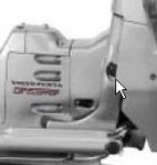
1. A previous thread from years back had a picture with the sensor location and testing procedures. Any chance these items can be posted again to assit me in my efforts?

2. The trim switch in my Morse Marine throttle is beginning to stick in the up position, requiring a counter control down to stop the trim motor from running. After removing the cover from the throttle, the culprit is a small switch with three wires (up, down, and nuetral I assume). No serial #, etc... to id. Any suggestions for finding a replacement?
 

Bondo

Moderator
Staff member
Joined
Apr 17, 2002
Messages
71,018
Re: 1996 Volvo SX tilt/trim sensor location

Ayuh,....

I haven't got Any answers for you,...
But,...
I'll bump this back up to the Top for ya.....
 

Don S

Honorary Moderator Emeritus
Joined
Aug 31, 2004
Messages
62,321
Re: 1996 Volvo SX tilt/trim sensor location

Here is the information from the manual on troubleshooting the trim sender and adjusting it.


Trim Sending Unit
Test Procedure

Remove sender from gimbal ring. Disconnect the sender 3-pin connector
inside the boat.
1. Attach an ohmmeter between the ?A? terminal ribbed black lead and
the terminal ?C? smooth black lead of the sending unit. Slowly rotate
the sending unit control nut counter clockwise until the ohmmeter is set
at infinity or open line (OL), then slowly rotate control nut counter clockwise
and ohmmeter will jump to 0 ohms. Continue to rotate control nut
for a highest ohmmeter reading of 600 ? 25 ohms.
2. Attach an ohmmeter between the ?A? terminal ribbed black lead and
the terminal ?B? white lead of the sender. Slowly rotate the sending unit
control nut counter clockwise until the ohmmeter is set at infinity or
open line (OL), then slowly rotate control nut counter clockwise and
ohmmeter will jump to a highest ohmmeter reading of 600 ? 25 ohms.
Continue to rotate control nut for a lowest ohm reading of 0 ohms.
3. Attach an ohmmeter between the ?C? terminal smooth black lead
and the terminal ?B? white lead of the sender. Slowly rotate control nut
counter clockwise. Ohmmeter should maintain a steady 600 ? 25 ohms.
If sender fails one of the three previous ohmmeter tests, replace the
sender.
Adjustment Procedure
1 1. Attach an ohmmeter between the ?A? terminal black lead and
the terminal ?C? black lead of the sending unit amphanol connector A .
Slowly turn the sending unit control nut until the meter reads 11 ? 1
ohm.
2 2. With the pivot housing pushed in towards the gimbal housing,
install and engage the sending unit control nut into the pivot bolt head.
Install two trim sender mounting screws B finger tight.
3 3. With the pivot housing pushed in toward the gimbal housing,
check adjustment of sending unit. Rotate sending unit to obtain a 11 ?
1 ohm reading on the meter, then tighten mounting screws to a torque
of 18-24 in. lb. (2.0-2.7 N?m).

The sender is located on the starboard side of the gimbal ring.

attachment.php
 

Attachments

  • Trimsender location.jpg
    Trimsender location.jpg
    7.7 KB · Views: 0
Top