1995 Black Max 150 grounding cable - is it necessary?

DJKaye

Cadet
Joined
Oct 22, 2013
Messages
11
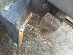
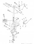
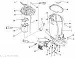
There is a small wire running from the bottom of the swivel bracket/steering arm to the bottom yoke. I just broke this while removing some corrosion with a wire brush. I assume this is a grounding cable to bond the exhaust tube and lower unit to the steering bracket. The wire isn't shown on the parts diagrams. Is this wire necessary? As far as I know I don't have any wires down in the lower unit, whatever was there originally is gone. I just have the water tube and the gear selector.
Thanks
 

Attachments

  • image.jpeg
    image.jpeg
    126.5 KB · Views: 5

DJKaye

Cadet
Joined
Oct 22, 2013
Messages
11
Ok thanks, if that is what it is, no problem because my trim indicator hasn't worked for the past 10 years or so. I set the trim by sound, tilt it up till it starts to cavitation then lower it a bit. My boat sits on the river all the time and it is a tough environment for things like tilt indicators, speed sensors, depth transducers,
Thanks.
 

sam am I

Commander
Joined
Jun 26, 2013
Messages
2,169
Np, Trying to recall however, I believe there is a rectangular anode situated at the base of the trim/tilt transom bracket.......It could double as a bonding as well, you'll have to look for an anode. I have one there on my 92.....

In theory, no system/component current is suppose to run in bonding but, merc may have cheated there I think
 
Last edited:

Dukedog

Captain
Joined
Oct 6, 2009
Messages
3,431
its a "bond" between tha down housing and clamp assy,.. upper and lower motor mounts have rubber inserts that supposedly isolate tha two...
 

DJKaye

Cadet
Joined
Oct 22, 2013
Messages
11
Thanks Dukedog, that is what I initially assumed it was. So what is the consequence of it not being there? I only use the boat infrequently for short trips up and down the river so it gets very little use but it sits in the river all the time and the heel of the keg is always immersed. None of the zincs are immersed while the motor is up. I have been surprised at how little corrosion/erosion there has been on the keg, sitting constantly immersed in a fast flowing river. It has bottom paint on it.
 

sam am I

Commander
Joined
Jun 26, 2013
Messages
2,169
Apologies if I wasn't clear..........I assume some think as twisted as I do

The problem here with merc's in this area is.........yes, it's bonded as Duke and I have indicated via this wire but,

The trim gauge's high side/signal wire is connected to the trim sender, so the sender mounted on the tilt/steering plate has voltage hooked to it via this wire, pretty simple so far so good...........Therefore it will/can have some current (milliamps, its current limited via the gauge's design) running through it back to its ground/return path.

Merc here however pulled a fast one and also uses the bonding (grounding) of the tilt/steering plate as the senders ground/return path via a mounting screw/ring lug arrangement AND your now broken wire.

Using bonding wires to carry current is a big no no for best practice bonding as this is a prime example of why it shouldn't be done...

YOUR wire to this tilt plate is now broken and the sender's current now will look for a ground path back to its source using whatever path it can find......This spells trouble and with salts, acidity and bases that are dissolved in water. The more, the better the electrolyte becomes, the more current can flow, the more metal can move.

I'd guess your Zinc, if conditions are fair, could be gone within month or two with a 10'ish ma. leak.

Corrosion will now rapidly consume things more so then just the weak battery form of **natural galvanic corrosion**. This, unlike the natural galvanic corrosion in dissimilar metals in water, this is direct current leakage which is far faster at eating things.

The current will seek the closest ground, hopefully this will be your bonded (grounded) lowest noble metal, your "Zinc". The Zinc/Al. will still be used as the sacrificially anode (as always being the most noble we have/use), but with now with a newly created cathode being made with trim/steering plate.

The current path will be from the highest noble metal, most likely being an unpainted stainless steel component in your tilt/steering assembly (bearing race, trim ram, etc.). When the Zinc is gone however, it's a crap shoot which goes next as you can guess. Theory says the next higher in line noble I reckon, which ever bit on your boat/motor that would be.

You can remove the power to the trim gauge as a work around but, since the bonding wire remains broken, you will still have un-bonded (floating) metal.

**Metals dissimilar suffer from the above mentioned natural galvanic corrosion because ionically dissimilar metals can form ever so slight potential differences between them and with an electrolyte present, small current flows between the metals, slowly carrying one metal to and depositing it on the other (corrosion). If the metals in questions are hard wired together (bonded), this prevents a "potential difference" from forming, no potential difference, no current flow, no corrosion.........Magic!!

You could however replace the $5.00 wire, just say'n.

**********The opinions expressed here are the views of the author and do not reflect the views and opinions of any employer or customer of the author. While every effort is made to ensure that the content is accurate, the opinion is provided ?as is? and I make no representations or warranties in relation to the accuracy or completeness of the information found on it. While the content of my opinion is provided in good faith, I do not warrant that the information will be kept up to date, be true and not misleading, or that this site will always (or ever) be available for use.********

This has been a recording............
 
Last edited:

DJKaye

Cadet
Joined
Oct 22, 2013
Messages
11
I am not so worried about the ground from the trim sensor. The battery is disconnected all the time except the relatively little time I run the boat. Anyway I can remove the wires to the trim sender and tape it off because it doesn't work anyway. I am more concerned about bonding the skeg which is in the water all the time to the metal on the bottom of the tilt mechanism. There is a big zinc on the bottom of that but I only get to see it once a year when I take the boat out of the water so I wouldn't see if it was being removed. My problem is where to attach the wire. The nut it connected to on the bottom yoke is too corroded to get it off. I also sheared the nut on the swivel bracket but that can be easily removed and replaced. So where should I run it to. The easiest available place seems to be the rear nut holding the footer. Any other suggestions of where to run a wire?
Thanks
 

sam am I

Commander
Joined
Jun 26, 2013
Messages
2,169
Not sure I follow.......


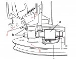
LU.jpgsender.jpg


The transom bracket (call-out 1) should already be bonded (check transom mounting bolts from bilge side, one should have a bonding wire to it). The LU (and its al/zinc trim tab [call-out 1]) has to already be grounded/bonded via battery neg cable at starter bolts. The tilt/steering swivel plate and yoke (call-out 2) are now floating however due bonding wire (near call-out b) being broken.

What I'd do then since it sounds as if we're in a pickle and can't replace the wire right now (and this is to limp us back from the Mars work around, but we'll be alive when we get home)

Since the trim sender/gauge is not working...perhaps we can still use it's wire working's for bonding

1) Dis-connect the high-side/signal wire from the trim gauge at the trim gauge (as you were going to do) that is connecting the gauge back to the trim sender that lives on call-out 2.

2) Use a multi-meter and measure the above mentioned at trim gauge removed wire to the grounding/mounting ring lug of the trim sender call-out 1a (If I recall right, the resistance of the sender is like around 320 ohms or some low'ish value near there)

If so (you were able to verify/measure this value to the grounding/mounting ring lug of the trim sender call-out 1a )......

a) Tie that wire to ground (not tape it off) and bond call-out 2 through the trim sender (bonding at 320 ohms to ground will work just ducky)

if not (the sender or wire leading to is open)

b) Cut the wire as it just enters the sender, crimp a ring lug on it and bond the new ring lug to the sender mounting ground screw.

c) Re-measure the wire to the grounding/mounting ring lug of the trim sender call-out 1a , it should be zero'ish ohms.

if so.....

i) tie the removed trim gauge wire it to ground as we did in step "a" above

if not(wire to sender is open)

ii) look for an open in the wire to the sender, fix the open, re-measure to the grounding/mounting ring lug of the trim sender to confirm and tie to ground.
 
Last edited:

sam am I

Commander
Joined
Jun 26, 2013
Messages
2,169
edit.........."The LU (and its al/zinc trim tab [call-out 3])" not "The LU (and its al/zinc trim tab [call-out 1])"

Also, the trim sender is wired as a rheostat so it should (if it still works) varies from 0'ish ohms up to some value like I guessed to be around 320 ohm. It actually (if we're lucky) might sit at 0 ohms with the LU down/in......I don't recall which it is thou.
 
Last edited:

DJKaye

Cadet
Joined
Oct 22, 2013
Messages
11
Wow, thanks for the detailed response. I will just replace the broken wire. Hopefully I can drill a small hole in the yoke and install a screw. Also what type of wiring ring connector should be used on boats? Mostly they are tinned copper, is that OK? I can't find stainless steel connectors.
Thanks
 

sam am I

Commander
Joined
Jun 26, 2013
Messages
2,169
No drill needed!!...........Just use call-out 1a's screw (call-out 1a is electrically a sub-assembly of and is mounted in call-out 2), The tilt/steering swivel plate and the yoke are all electrically common to this screw and grounding through the sender(jumperd if you have too)/new wire will bond that whole assembly to ground.

Well tinned copper I'd think would last for awhile, I think that's what merc used on the trim sender crimped ring lug.
 
Last edited:

sam am I

Commander
Joined
Jun 26, 2013
Messages
2,169
Correction..........The yoke is electrically common to the LU as seen above via bonding wire call-out d (slightly off the page at bottom).

This stainless wire (identical to the broken one) is hidden under a plastic plate and it probably okay, you might want to verify that with a multi-meter to ground.

Your wire that broke then bonds call-out 2 via the yoke bolt call-out b. The tilt/steering swivel plate only is electrically common to this screw call-out 1a.

Bonding tilt/steering swivel plate via the trim senders highside/signal wire that is removed from the trim gauge, then grounded and
  1. Through the trim sender (if the rheostat is still good) or just..
  2. Cutting the highside/signal wire at the sender and adding a ring lug and mounting it to call-out 1a

are both still a perfectly valid workarounds until you can replace the broken bonding wire.The yoke remains as is, bonded via LU/battery neg cable then via bonding wire call-out d (slightly off the page at bottom) hidden under a plastic plate.
 
Last edited:

Dukedog

Captain
Joined
Oct 6, 2009
Messages
3,431
ya'll or gettin' a little off base... tha trim sender ground can screw inta tha same piece its mounted to... tha "broken bond" is just a jumper around tha motor mount... one end goes under tha bolt head or one of tha bolts holdin' tha motor mount in place and tha other goes under tha nut on tha yoke.....so yeah,, tap it inta tha yoke... won't hurt a thing ta run like it is with a "crusty" motor anyway.....
 
Last edited:

sam am I

Commander
Joined
Jun 26, 2013
Messages
2,169
Hehehe, perhaps duke and usually out of the stadium even, and yes, no doubt old and crusty but seriously......When the bond wire from the yoke nut to the transom bracket bolt breaks or bond wire around the motor mount breaks, the trim sender goes nuts jumping around because both wires complete a ground path for the piece the trim sender's ground mount. The mounting piece electrically floats up and the trim gauge has a s**t ground..........

If you then leave the now floating mount piece electrically energized via the gauge and sender's rheostat, the anode/s will go fast, mine started too even in fresh water when my bond wire broke like his did. I didn't take notice until my trim gauge needle starting going nuts jumping full scale every time I'd raise or lower the LU.

Took me a bit to figure it out, though the sender crapped but, the damn bond wire had broke and looked burnt in half!! I also noticed the al/zinc trim tab was looking ate up..Never had that issue in the 25 yrs in the same waters, same trim tab and poof, the leading edge of the trim tab was being ate up in one season.
 
Last edited:

Dukedog

Captain
Joined
Oct 6, 2009
Messages
3,431
two seperate things.. tha clamp brackets AND sadle (part tha trim sensor is mounted on) are already grounded thru tha power head ground.... tha broken wire is strickly for a jumper around tha rubber motor mount.....in theoy (anda brand new motor with all fresh paint) tha down housing and lower unit are isolated by tha rubber in tha upper and lower motor mounts...(in real life it isn't 99.9% of tha time 'cause of tha power head studs tha go all tha way thru tha down housin')... tha rest of tha thing should be grounded tha instant ya make up battery ground... if your sensor acted up cause of tha bonding jumper broke, ya got other problems......
 
Last edited:

sam am I

Commander
Joined
Jun 26, 2013
Messages
2,169
two seperate things.. tha clamp brackets AND sadle (part tha trim sensor is mounted on) are already grounded thru tha power head ground....

I have to respectfully disagree Duke........I still however will bow to your many years on these things, I can't even begin to hold a candle to it...........

1) Power head, mid section, LU are all hard bolted together and then by default are then all electrically tied together, yes. The battery neg/ground cable then bolts on at starter into power head. Think we'd agree there?

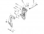
2) Below.......Left (call-out 1) and right (call-out 2) clamps ("transom brackets") are electrically tied together via a hard bolted (call-out 6, 9) tilt tube (call-out 5) that runs between them. They are then bonded via a wire on any of the transom mount bolts (call-out 9), typically on bilge side bolt head.


1.jpg


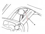
3) Below.......The saddle ("swivel bracket [call-out 1]) that the trim sensor (call-out 23) is mounted/grounded too of course sits between the left and right above transom brackets and pivots on tilt tube via bushings (the bushings/bearing in the tilt tube are not used/never for ground path/s......they sorta conduct at times and different positions, I think that's where I was getting a secondary crap ground from as I raised and lower the motor when my ground wire call-out 7[next image below]) ).

4) Below....The swivel pin and steering arm (call-out 18) go through the swivel bracket and 4 bolts (call-out 9 x 2 and call-out 3[next image below]) to hold and swivel the power head, mid section, LU. The 4 bolts (two through lower yoke (call-out 19) and 2 through steering arm (call-out 18) however are steel collared rubber motor mounted (call-out 10 x 2 and call-out 5 x 2[next image below]).

2.jpg


5) Below.......These 4 steel collared solid rubber motor mounts by default electrically isolate the through bolt from the clamp-in steel collars and are all clamped into the mid section plate (call-out 30) and LU drive shaft housing (call-out 1).

6) Below......The ground path for the trim sender then is via "ground wires" (call-out 4 and call-out 7). The wires then electrically tie/bond the swivel bracket via screw (call-out 9) to the Power head, mid section, LU via bolt (call-out 3).


3.jpg
 
Last edited:

sam am I

Commander
Joined
Jun 26, 2013
Messages
2,169
Correction (geeesh, pasted wrong image)........should read "hard bolted (call-out 5, 8) tilt tube (call-out 4) that runs between them", not "hard bolted (call-out 6, 9) tilt tube (call-out 5)that runs between them."
 
Last edited:

Dukedog

Captain
Joined
Oct 6, 2009
Messages
3,431
'lectrics, especially DC, can and do some strange things on occasion....factory paint (especially on tha down housin') has a big part with ground path on these things (also corrosion on power head studs on old stuff) ... thats why i included "new"......down housing and gear case can show a good ground without those jumpers when tha motor is silent (thru driveshaft) but once tha bearings start turnin' it changes..... jan, those "rubber" mounts were "always" tha first in tha trash, with my (production) junk anyway!..

"They are then bonded via a wire on any of the transom mount bolts (call-out 9), typically on bilge side bolt head".

curious?... no one (dealers included) around here add a ground to any of tha thru transom bolts?... is that something done in your neck a tha woods?
 
Last edited:

sam am I

Commander
Joined
Jun 26, 2013
Messages
2,169
They are then bonded via a wire on any of the transom mount bolts (call-out 9)

.curious?... no one (dealers included) around here add a ground to any of tha thru transom bolts?... is that something done in your neck a tha woods?

Good question and of course I haven't seen/checked all that many boats, not like hundreds anyway, just a handful over the years and I THINK i've seen this here and there. Maybe it's more common with I/O? So i just assumed it was standard practice and mine had it from the factory, yes.

Perhaps they are thinking/doubling the rectangle anode that is screwed to it as a makeshift dynaplate for like lightning, RF/VHF and the likes, not sure.

I mainly guessed it was to make sure the rectangle anode that is screwed it to was hard tied to ground. Boat was built over here on the salty left coast, so not sure. Heck, the manu even bonded the drain plug brass housing, a brass live well sea **** valve all in the bonding wire daisy chain that untimely ends up to the neg battery. Maybe this manu just went nuts bonding anything that went through the transom or hull that was metal.........
 
Last edited:
Top