1981 Johnson 115 voltage regulator

ruddy mudder

Seaman Apprentice
Joined
Oct 1, 2009
Messages
45
1981 115 voltage regulator, not sure how it works or what it is for. Will it affect the charging of the battery if it goes bad? How is this component tested to see if it is good? Does this act more as a resistor seeing as the purple wire is keyed power and yellow is on charging terminal. Thanks for any help.
 

flyingscott

Fleet Admiral
Joined
Apr 8, 2014
Messages
8,095
It is also a rectifier that converts AC to DC voltage. If it goes bad your battery will not charge. Pretty important part of the charging system.
 

Vic.S

Rear Admiral
Joined
May 4, 2004
Messages
4,718
I think you will find that model has a separate rectifier and regulator.
If without power tilt and trim in has a 6 amp stator and a simple ( round, 3 wire ) rectifier to convert AC to DC for battery charging.
If with power tilt and trim it has a more powerful (10 amp) stator and a regulator in addition to the rectifier. The regulator controls the voltage to prevent overcharging the battery which could otherwise occur with the more powerful stator..

Probably the easiest way to test the regulator is to monitor the voltage at the battery . If the regulator is OK you should see the volts rise to something around 14 to 14.4 volts but not rise significantly higher even when the battery is fully charged.

Replacement regulators are no longer available but if necessary the rectifier can be replaced with a CDI regulated rectifier.
 

ruddy mudder

Seaman Apprentice
Joined
Oct 1, 2009
Messages
45
Purchased two new 3 wire rectifiers from Pro Marine and when tested with an ohm meter, I get different readings on the wires which according to the OMC manual makes them defective. Are Pro Marine products such as rectifiers reliable components?
 

Crosbyman

Vice Admiral
Joined
Nov 5, 2006
Messages
5,450
3 wire rectifiers are simply diodes wired up to convert the 2 inputs (AC phases) to a single DC output.... without regulating to ouput. parts listing shows a simple round full phase rectifier . IF overly expensive they are available on Amazon dirt cheap with lots of amp capacity. mounted properly they will do the job. Up to you

2 x AC posts either way connected ...will rectify the AC . the + post goes the regulator if you have one or goes tp the solenoid main battery post to charge the battery. the - (neg) post goes to ground . As I said .. up to you if you feel comfortable with this solution .


are you testing your new units connected to anything or alone on the bench ????
 
Last edited:

ruddy mudder

Seaman Apprentice
Joined
Oct 1, 2009
Messages
45
3 wire rectifiers are simply diodes wired up to convert the 2 inputs (AC phases) to a single DC output.... without regulating to ouput. parts listing shows a simple round full phase rectifier . IF overly expensive they are available on Amazon dirt cheap with lots of amp capacity. mounted properly they will do the job. Up to you

2 x AC posts either way connected ...will rectify the AC . the + post goes the regulator if you have one or goes tp the solenoid main battery post to charge the battery. the - (neg) post goes to ground . As I said .. up to you if you feel comfortable with this solution .


are you testing your new units connected to anything or alone on the bench ????
Testing them on the bench, can't believe two new ones would both be bad, but according to the manual they are. Put the first one on the engine and voltage was at 12.5 volts, checking at the battery, solenoid and bus bar. These parts must be made overseas as the price is very attractive, who knows where BRP gets them made from. Very discouraging for new ones not used to not work, may just have to bite the bullet and get an OMC part from the dealer. Thanks for your reply!
 
Last edited:

Crosbyman

Vice Admiral
Joined
Nov 5, 2006
Messages
5,450
no offense... did you test resistance from AC (yellows) to the red wire output only

continuity (low resistance) should exist one way only either yellows to red
no continuity from RED to yellows.
 

racerone

Supreme Mariner
Joined
Dec 28, 2013
Messages
37,851
Buy from your local dealer.-----They get to know you.----I do not buy wiper blades for my truck from a big box store.-----If there is an issue I deal direct with the owner.----No need to go through the " you need a receipt " scenario at the faceless store or internet !!
 

Crosbyman

Vice Admiral
Joined
Nov 5, 2006
Messages
5,450
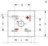
but... if you choose the Amazon solution here is the pin layout

yellow wires to AC pins + is the battery last pin is ground.
 

Attachments

  • rectifier pins.JPG
    rectifier pins.JPG
    44.5 KB · Views: 0

ruddy mudder

Seaman Apprentice
Joined
Oct 1, 2009
Messages
45
no offense... did you test resistance from AC (yellows) to the red wire output only

continuity (low resistance) should exist one way only either yellows to red
no continuity from RED to yellows.
No offense taken. Yes, got reading on one wire only, even after reversing the the leads.
 

ruddy mudder

Seaman Apprentice
Joined
Oct 1, 2009
Messages
45
Will testing the yellow wires with the engine running from the alternator show a voltage going into the rectifier? What AC setting would be sufficient to pick up the out put from the stator (6 amp)? The stator ohms tested good and I now have a good rectifier but still do not have over 12.5 volts at the buss, solenoid and battery when running. I have even tried another flywheel and still no charging voltage. Getting a little desperate to get this problem solved, any more suggestions?
 

Crosbyman

Vice Admiral
Joined
Nov 5, 2006
Messages
5,450
in theory if you expect a charging voltage around 14v the yellows should generate equal of slightly above 14 volts . the two "alternating" ac swings (+/-) will be redirected into your single + ouput voltage from the rectifiers diodes .

set your meter to 50-100v AC and probe the yellows with engine running above idle
 
Top