Please have a look at these wiring pics. 1994 Force 40HP

32251

Petty Officer 3rd Class
Joined
Jul 14, 2009
Messages
85
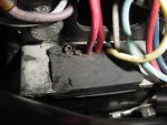
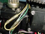
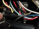
What is your opinion of these wiring pics. If you look closely you can see two wires that seem to have been cut on this part. I don't really know what this part is...rectifier????. It is located on the left side of the motor looking at the back way down almost at the base. Also coming off one of the corners where it is bolted down is a black ground wire that goes no where. You can see where it connects in the first pic and see the end of it in the other pic. I can't tell what was grounded to it. In the other pic you can see a group of four wires that comes from under the flywheel. Two are yellow. One of the yellow wires is not hooked up to anything. It was just lying down in the bottom of the engine housing sparking. Can someone give me an assessment of this wiring. The boat cranks and runs, but not smooth. I have been told that the yellow wire is part of the rectifier circuit. Thanks for any help.
 

Attachments

  • MVC-021S.JPG
    MVC-021S.JPG
    36.4 KB · Views: 0
  • MVC-024S.JPG
    MVC-024S.JPG
    37.8 KB · Views: 0
  • MVC-023S.JPG
    MVC-023S.JPG
    36.1 KB · Views: 0

foodfisher

Captain
Joined
Feb 18, 2009
Messages
3,756
Re: Please have a look at these wiring pics. 1994 Force 40HP

Consult the wiring diagram in your manual.
 

sweezy722

Petty Officer 3rd Class
Joined
Feb 5, 2007
Messages
78
Re: Please have a look at these wiring pics. 1994 Force 40HP

My manual shows 4 wires coming from the rectifier and that is what it looks like to me - however I am not familiar with the 94 model. The 4 wires listed are 2 yellow wires coming from the stator - one red wire to a positive battery connection to recharge the battery - and a gray wire to the tachometer.

http://www.boats.net/parts/search/M... THRU 0E093699/IGNITION COMPONENTS/parts.html

Look at this picture above - it may be the switch box. Good luck.
 

32251

Petty Officer 3rd Class
Joined
Jul 14, 2009
Messages
85
Re: Please have a look at these wiring pics. 1994 Force 40HP

That looks more like part number 14--Reg.volt box. Maybe this is a replaced voltage regulator box that is not needing the two cut wires??? OK so where in the heck does the yellow wire connect and where does the mystery ground wire that is connected to the right hand bolt that holds the Reg.volt box on connect too?
 

32251

Petty Officer 3rd Class
Joined
Jul 14, 2009
Messages
85
Re: Please have a look at these wiring pics. 1994 Force 40HP

Consult the wiring diagram in your manual.

I do have the manual for the motor, but consulting a wiring diagram and consulting someone on this forum are two different things to me!
 

sweezy722

Petty Officer 3rd Class
Joined
Feb 5, 2007
Messages
78
Re: Please have a look at these wiring pics. 1994 Force 40HP

Something caused the wires to burn into. If it were my motor I would be working to get it like it should be. I am guessing you need to replace the voltage regulator and fix the wiring to match what the original was. That is a high priced voltage regulator. However, I do not think your charging system will work properly with only 1 lead from the stator. The 2 yellow wires come from the stator with 240 volts AC and the rectifier breaks it down to 12 volts DC - if I remember correctly. Those yellow wires pack a heck of a punch. Do not make the mistake of grabbing one while the motor is running. I can tell you it hurts alot.
 

32251

Petty Officer 3rd Class
Joined
Jul 14, 2009
Messages
85
Re: Please have a look at these wiring pics. 1994 Force 40HP

When I was testing the motor initially, it was late in the afternoon and when the sun started going down I saw the flashes up under the wiring as the motor was running and I knew that something was arcing. I was hoping to just find a wire that had burned into and then I would just repair that and all would be fine...NOT. The ground wire going to nowhere and the yellow wire going to nowhere and they are not supposed to be hooked together from what I gather. I am going to study the wiring diagram in my manual real good and see what I can figure out. I have called a couple of tech/mechanic types and when I get a good idea of what is going on, I am going to take it to them and have all the electricals tested and then decide what to do. I did not just want to show up and leave the boat/motor and let them charge me $100 an hour to do what they wanted. Found a guy who will test the electrics and tell me what it needs for $35 an hour.
 
Top