1975 135HP Stator and Timer Base

Randyg123

Petty Officer 1st Class
Joined
Apr 20, 2008
Messages
337
Okay, I pulled the Flywheel off last night without a hitch. (But I admit when that thing went "POP!!!!!", I thought I snapped something:eek:

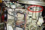
Everything looks okay underneath so far.

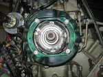
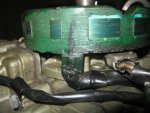
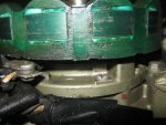
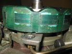
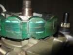
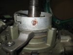
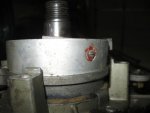
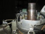
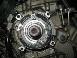
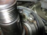
What are some things to look for? I want to make sure everything is correct underneath since my timing is an issue. I took some photos of the stator and how it is set. Does everything look correct and is this the correct stator? Is there a part number? If you look at the to view closely, you can see that my timing stop is screwed all the way in to get the WOT correct (per Joe Reeves method).

Tonight if I have time, I will pull the stator off (any hints, anything to watch out for, should I leave it alone?) to get a good look at the timer base.
 

Attachments

  • Top View.jpg
    Top View.jpg
    75.1 KB · Views: 0
  • Port bow View.jpg
    Port bow View.jpg
    61.1 KB · Views: 0
  • Port Aft View2.jpg
    Port Aft View2.jpg
    63.9 KB · Views: 0
  • Starboard Aft view.jpg
    Starboard Aft view.jpg
    57.8 KB · Views: 0
  • Starboard Bow view.jpg
    Starboard Bow view.jpg
    49.5 KB · Views: 0

Randyg123

Petty Officer 1st Class
Joined
Apr 20, 2008
Messages
337
Re: 1975 135HP Stator and Timer Base

Bump^^^
I have pretty pictures ;)
 

iwombat

Captain
Joined
Jul 12, 2006
Messages
3,767
Re: 1975 135HP Stator and Timer Base

Nothing tricky about the stator, just pull it up and flop it over (leaving the wires attached). I don't see anything weird so far. But, I'd like to get a better look at the stator coils and their mounts.

I've also been wondering if maybe you've got the wrong flywheel on there.
 

Randyg123

Petty Officer 1st Class
Joined
Apr 20, 2008
Messages
337
Re: 1975 135HP Stator and Timer Base

Nothing tricky about the stator, just pull it up and flop it over (leaving the wires attached). I don't see anything weird so far. But, I'd like to get a better look at the stator coils and their mounts.

And how might I accommodate you on this issue? More pictures! I can do that. How do i get a good shot of the stator coils and their mounts. Are these going to be visible?
 

iwombat

Captain
Joined
Jul 12, 2006
Messages
3,767
Re: 1975 135HP Stator and Timer Base

'scuse me. I meant timer base coils. Oops.
 

ezeke

Supreme Mariner
Joined
Sep 19, 2003
Messages
12,532
Re: 1975 135HP Stator and Timer Base

I've never seen a stop set so far in before, normally they look more like the one in the thumbnail.
 

Attachments

  • 1975 stop.JPG
    1975 stop.JPG
    28.5 KB · Views: 0

Randyg123

Petty Officer 1st Class
Joined
Apr 20, 2008
Messages
337
Re: 1975 135HP Stator and Timer Base

I've never seen a stop set so far in before, normally they look more like the one in the thumbnail.

That is why I am so puzzled as to what the heck is going on with my timing. I even bought a new stop and linkage just to make sure there was no Frankenstein stuff going on here.

I keep hoping for that "a-hah" moment and it never comes.
 

iwombat

Captain
Joined
Jul 12, 2006
Messages
3,767
Re: 1975 135HP Stator and Timer Base

Yep me too.

I'm guessing wrong timer base or wrong flywheel.
 

Randyg123

Petty Officer 1st Class
Joined
Apr 20, 2008
Messages
337
Re: 1975 135HP Stator and Timer Base

Okay, I removed the stator exposing the timer base. Before I remove that, here are some photos. Any 'a-hahs' yet?
 

Attachments

  • IMG_0078.jpg
    IMG_0078.jpg
    42.1 KB · Views: 0
  • IMG_0080.jpg
    IMG_0080.jpg
    37.1 KB · Views: 0
  • IMG_0083.jpg
    IMG_0083.jpg
    40.8 KB · Views: 0
  • IMG_0084.jpg
    IMG_0084.jpg
    64.8 KB · Views: 0
  • IMG_0085.jpg
    IMG_0085.jpg
    43.3 KB · Views: 0

iwombat

Captain
Joined
Jul 12, 2006
Messages
3,767
Re: 1975 135HP Stator and Timer Base

Well, that sure looks like the right timer base. Also looks like someone has cracked the epoxy and adjusted the coil gap. Should either work or not though and doesn't explain what you're seeing. What about the flywheel?

Edit: Ok, here's theory #7. Are the wires from the timer base attached to the power pack correctly?
 

Randyg123

Petty Officer 1st Class
Joined
Apr 20, 2008
Messages
337
Re: 1975 135HP Stator and Timer Base

Well, that sure looks like the right timer base. Also looks like someone has cracked the epoxy and adjusted the coil gap. Should either work or not though and doesn't explain what you're seeing. What about the flywheel?

Edit: Ok, here's theory #7. Are the wires from the timer base attached to the power pack correctly?

I'll confirm the wiring.

Flywheel part number is 581044.
The BRP parts site says it should be a 581045

Is there a difference????
 

iwombat

Captain
Joined
Jul 12, 2006
Messages
3,767
Re: 1975 135HP Stator and Timer Base

Flywheel magnet position in relation to the keyway in relation to the timer base pickup coils is what sets the timing.

I'm thinking you need the correct flywheel.

Although 581044 is probably a casting number, and may or may not be the part#.

Little help needed on that one.
 

Randyg123

Petty Officer 1st Class
Joined
Apr 20, 2008
Messages
337
Re: 1975 135HP Stator and Timer Base

Well, that sure looks like the right timer base. Also looks like someone has cracked the epoxy and adjusted the coil gap. Should either work or not though and doesn't explain what you're seeing. What about the flywheel?

Edit: Ok, here's theory #7. Are the wires from the timer base attached to the power pack correctly?

Okay, I can confirm that at the Powerpack the cables marked Sensor 1, Sensor 2, Sensor 3, and Sensor 4 are connected to the correct terminals. What I cannot confirm is that the two timers are in the correct position on the timer base (i.e. they are not switched). I assume it wouldn't even run if this is the case. But no assumptions will be made at this point. Can it be confirmed?
 

iwombat

Captain
Joined
Jul 12, 2006
Messages
3,767
Re: 1975 135HP Stator and Timer Base

It probably wouldn't run unless one is out completely AND they're swapped. But I don't think we need to go there yet.
 

Randyg123

Petty Officer 1st Class
Joined
Apr 20, 2008
Messages
337
Re: 1975 135HP Stator and Timer Base

It probably wouldn't run unless one is out completely AND they're swapped. But I don't think we need to go there yet.

I was looking for a way to test continuity but was afraid I might damage the sensor some how.
Would a DVM cause any problems? I could check that.

But as for the sensors, I guess they should be okay as I tested them last week, I think, better check my notes!
 

Randyg123

Petty Officer 1st Class
Joined
Apr 20, 2008
Messages
337
Re: 1975 135HP Stator and Timer Base

I was looking for a way to test continuity but was afraid I might damage the sensor some how.
Would a DVM cause any problems? I could check that.

But as for the sensors, I guess they should be okay as I tested them last week, I think, better check my notes!

Yep, checked 'em - 9.2 and 8.9 ohms at 90F no shorts either.
 

ezeke

Supreme Mariner
Joined
Sep 19, 2003
Messages
12,532
Re: 1975 135HP Stator and Timer Base

Flywheel with casting # 581044 is OK.
 

Randyg123

Petty Officer 1st Class
Joined
Apr 20, 2008
Messages
337
Re: 1975 135HP Stator and Timer Base

Dang!

No a-hah moment once again.

So the timer base looks correct, the stator looks correct, the flywheel looks correct. yet my timing adjustment must be set all the way in to meet the WOT. Any other ideas?

Timing has been set by two individuals and me all come up with the same setting.
 

ezeke

Supreme Mariner
Joined
Sep 19, 2003
Messages
12,532
Re: 1975 135HP Stator and Timer Base

Do you have the sensors wired to the powerpack correctly?
 

Attachments

  • Powerpack Instructions.JPG
    Powerpack Instructions.JPG
    77.9 KB · Views: 0

Randyg123

Petty Officer 1st Class
Joined
Apr 20, 2008
Messages
337
Re: 1975 135HP Stator and Timer Base

Do you have the sensors wired to the powerpack correctly?

I'm not at home (darn employment!) but as I discussed with iwombat, I confirmed that the wires coming from the timer base are labeled (Sensor 1, Sensor 2, Sensor 3, and Sensor 4). These are the mfg labels. Each of these go to their corresponding labeled point on the Power Pack (As shown on the PowerPack cover label).

I have not confirmed that the actual wire labels are correct (no reason to believe they wouldn't be) or that the coils are not reversed in the timer base (i.e. the 1-3 coil is in the 2-4 position and the 2-4 coil is in the 1-3 position).
 
Top