Wiring Diagram

default83

Recruit
Joined
Jun 3, 2008
Messages
3
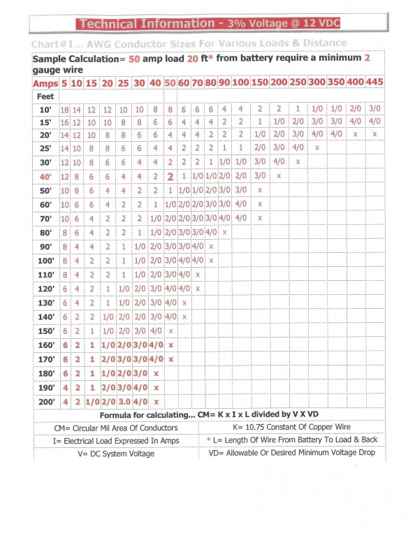
HEy guys, i made this for my buddies bass boat, i just wanted some opinions and advice as far as wiring options that i have and if im doing anything wrong, this is my first time wiring a boat but have heard its good to create a diagram of it before starting, so here it is, just any advice is good Thanks Guys!
 

Attachments

  • FUSE Model (1).pdf
    17.7 KB · Views: 0
  • FUSE Model (2).pdf
    16.8 KB · Views: 0
  • FUSE Model (3).pdf
    14.1 KB · Views: 0
  • FUSE Model (4).pdf
    10.3 KB · Views: 0

KnottyBuoyz

Senior Chief Petty Officer
Joined
Mar 6, 2006
Messages
712
Re: Wiring Diagram

Excellent start. One suggestion that jumps out. On the third drawing move the breaker (or fuse) for the trolling motor back as close to the battery as you can. It should be ideally within 1 foot of the battery. Run the battery cables for the trolling motor up the port side to shorten them as much as possible. Find out the full current draw in Amps for the trolling motor and size your cables to carry the load. Remember when you're calculating circuit length it's to and from the load to the battery so if the trolling motor is 15' from the battery the total circuit length is 30'. Ideally you're trying to keep <3% voltage drop from battery to trolling motor.

79voltagedroptable-med_original.jpg


So from this chart if the total circuit length is 30' and the trolling motor draws 30 amps the wire size would be 4Ga. But, bigger is always better unless cost is a factor.

Personally I would add a second battery to service the trolling motor. With only one charging device (alternator) you run the risk of killing the battery with the trolling motor and have no way to start the engine. Plenty of threads on here describing this situation and how to get around it. I'm a fan of "Automatic Charging Relays" to charge two batteries, while keeping them separate for discharging. This way if the trolling motor battery goes flat you can still start your boat which will charge the battery and get you home.
 

Silvertip

Supreme Mariner
Joined
Sep 22, 2003
Messages
28,762
Re: Wiring Diagram

Your NAV wiring is also incorrect. The switch that controls NAV lights is a center OFF three position switch. In one position both the nav lights (red/green) and the anchor/all around light (white) are on. In the other position ONLY the white anchor/all around light must be on. There are two ways to do this.

Nav-AnchorSwitch.jpg


or

NavSwitchWiring.jpg
 

gsk2005uk

Seaman
Joined
Apr 7, 2008
Messages
62
Re: Wiring Diagram

As I am a newbie with these things, what kind of a diode should I place on the on-off-on switch? How do I ask it in the store? The navi lights are as shown on the picture and connected on a 12V battery.
 

DRIFTER_016

Petty Officer 1st Class
Joined
May 5, 2008
Messages
360
Re: Wiring Diagram

I would run a 100 volt 6 amp Rectifier diode.
You could probably get away with a 3 amp but the 6 amp will run cooler and have less of a chance of burning out.
I like to over engineer things!! :D
FYI, if you install it backwards only one light will work.

The second method using the DPDT switch is easier. IMO
 
Top