trailshredder
Petty Officer 1st Class
- Joined
- Apr 25, 2011
- Messages
- 283
With the key on, I have 2 purples with 12v, one purple with 0 and the ground.


With the key on, I have 2 purples with 12v, one purple with 0 and the ground.
I have 12 volts on 2 of the 3 purple wires, when the ignition is in the on position and 12 volts on all three when in the start position (cranking).
How do I know if I have the GL-A or GL-E to use your wiring diagrams?
| American Boat and Yacht Council Standards | � | |
| COLOR | ITEM | USE |
| Black | Ground | Negative / Neutral Main Return |
| Blue-Stripe | Tilt up and or trim out | Tilt and or trim circuits |
| Brown | Alternator Charge Light | Generator Terminal or Alternator Auxiliary Terminal to Regulator |
| Brown | Generator Armature | Generator Armature to Regulator |
| Brown | Pumps | Circuit Breaker or Switch to Pumps |
| Brown w/Yellow | Bilge Blowers | Circuit Breaker or Switch to Blower |
| Dark Blue | Cabin & Instrument | Circuit Breaker or Switch to Lights |
| Green or Green w/Yellow Stripe | Bonding System | Grounding Wires (if insulated) |
| Green Stripe | Tilt down and/or trim in | Tilt and or trim circuits |
| Grey | Navigation Lights | Circuit Breaker or Switch to Lights |
| Grey | Tachometer | Tachometer Sender to Gauge |
| Lt. Blue | Oil Pressure | Oil Pressure Sender to Gauge |
| Orange | Accessory Feed | Ammeter to Alternator or Generator |
| Orange | Common Feed | Distribution Panel to Accessory Switch |
| Orange | Feed | Accessory Circuit Breakers or Switches |
| Pink | Fuel Gauge | Fuel Gauge Sender to Gauge |
| Purple | Ignition | Ignition Switch to Coil & Electrical Instrument |
| Purple | Instrument Feed | Distribution Panel Electrical Instruments |
| Red | Power Feeds | Positive Main Power (particularly un-fused) |
| Tan | Water temperature | Water temperature sender to gauge |
| Yellow | Generator Field | Generator to Regulator Field Terminal |
| Yellow | Ground | Negative / Neutral Main Return |
| Yellow w/Red | Starting Circuit | Starting Switch to Solenoid |
Helm wiring
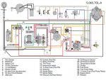
Appreciate it! What is item 17 on the diagram?
Appreciate it! What is item 17 on the diagram?