1973 mercruiser MR-1 888 without gimbal mounted limiter switch

Status
Not open for further replies.
Joined
Aug 18, 2018
Messages
6
Hey guys new to the forum but have enjoyed the knowledge before becoming a member. Thanks to all those who share and build info for others. So the reason i am here i am restoring a 1973 AMF slickcraft SS235hardtop for lake michigan salmon fishing. I have ran into a snag in regards to the wiring for the tilt/trim, this is the older style single solenoid pump without a gimbal mounted limiter switch "has hydraulic switch mounted to the inside of the transom" I could use a wiring diagram as i am trying to figure out where the 2 wires of the harness side "purple and light blue" go.... also the how 2 hook the hydraulic switch up as it only has one purple wire and ground i believe... i have a trim gauge also and want to make sure i am able to get it to work along with proper function of the 3 button trim up, down, trailer mode. Currently it works going up "trailer mode middle button and up" and down .... not sure if it works for the trim function will have 2 test again. I just want to be sure i am able get the trim gauge working so i can make sure not 2 over trim and damage u-joints. Thanks for any help
 

alldodge

Moderator
Staff member
Joined
Mar 8, 2009
Messages
42,268
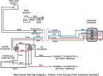
Think your biggest issue is finding parts for the old design. Don't know if you have a 1 or 2 solenoid trim system so here is both.

Unless your doing a restore for 100% accuracy, might thing about replacing the system with new design


Power Trim 1 Solenoid.jpg

Power Trim 2 Solenoid.jpg
 

kenny nunez

Captain
Joined
Jun 20, 2017
Messages
3,311
To replace the trim limit switch on your model is not worth the trouble. That switch usually lasted until the engine was out of warranty. The best thing you could do would be to find a 1976 - 85 model gimbal housing. You will just have to trim some transom material and drill 2 new mounting holes. Replace all the wires and switches on the gimbal ring and of course replace the shift cable and bellows. Also the Old style push buttons get corroded but can be disassembled and the contacts cleaned. There are 2 copper contact points and the copper contact on the button gets distorted from pushing it too hard further aggravates the problem.
 

Bt Doctur

Supreme Mariner
Joined
Aug 29, 2004
Messages
19,311
Untitledet.jpg
 
Joined
Aug 18, 2018
Messages
6
Thanks for all the info.... the boat is currently back together as in new motor is in and gimbal housing bolted in and sealed up agaist a brand new transom. Thanks for wiring diagrams as well as the how to check gauge and electric trim sender.... the only question i really still have yet 2 answer is even the diagrams posted show a gimbal mounted trim limit switch.... as stated in original post this early model did not have a limit switch so i am not sure where the blue wire at the harness goes... was it left loose, or is it supposed to tie into the electric trim sender..... cause i dont see how the system would operate without some sort of limit signal? So i was out in the boat today working on install of duel battery setup and making battery cables.... got it all wired up and now have a question in regards to the 10 pin "9 used" engine harness does anyone have a pinout of that connector as i have 12.56 volts at the red wire which goes to the voltage gauge, however i dont have anything at the orange wire which goes to gauges and then to a fused ignition lead?
 

kenny nunez

Captain
Joined
Jun 20, 2017
Messages
3,311
The trim limit switch was located at the top of the gimbal ring. There was a button concealed with a metal “finger” that contacted the top of the bell housing, as the drive was trimmed there is a “high spot” that moved away from the metal finger that released the button which broke the circuit. To replace the button the gimbal ring has to come out. Most likely the gimbal ring was replaced in the past and the switch was not re-installed.
 
Joined
Aug 18, 2018
Messages
6
I had the entire gimbal ring out as the while transom has been redone. When i had it all appart i never saw the limit switch or signs of one ever being there. Also did not see anywhere where a wire could have went. I was under the understanding this 1973 888 outdrive was never equiped with one. Well at this point i can live without a limit switch function. Any idea what the max safe operating trim is, as once i know i can stay within the limits. Thanks for your help this could likely be very possible and i am not going to lose sleep over it. I will attempt to get the trim indicator wired up and run it that way. Also do you by chance have the mercruiser 188 engine harness/ hull side diagram? The one above might be different.
 

achris

More fish than mountain goat
Joined
May 19, 2004
Messages
27,468
The limit switch is up under the top of the gimbal ring. Difficult to see if you're not looking for it...

The operations of the trim panel is as follows. Trim down, press the bottom 'IN' button. To trim up form fully, or near fully, down (assuming the limit switch is working and wired in), press the centre 'UP' button. The drive will stop going up at about 1/2 way. To tilt further, press the top button, 'OUT' and the centre button, 'UP' together.
This will take the drive all the way up... Now, if the limit switch is faulty, or not connected, the centre button will not work, at all. To get the drive up in this circumstance, press top and centre buttons together. If that gets 'old, as it will very quickly, just use a short jumper between the connections that the limit switch plugs into. That will allow the centre 'UP' button to bring the drive all the way up. So be aware of that, and don't over trim.... ;)

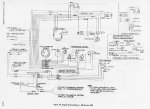
Here is a circuit diagram for your engine. The drawing includes all instruments, and the trim wiring, including the reverse lock valve that wasn't in the one above...

Click image for larger version  Name:	888wiring.JPG Views:	1 Size:	150.6 KB ID:	10638638

Chris......
 
Last edited:

Bondo

Moderator
Staff member
Joined
Apr 17, 2002
Messages
70,985
Any idea on safe max operating trim?

Ayuh,...... When ya loose speed, or the hull porpoises, yer trimmed too high,....
 

achris

More fish than mountain goat
Joined
May 19, 2004
Messages
27,468
As Bondo said.

The official setup is that under operation, the drive should not be raised beyond the point where it comes out of the side supports on the gimbal ring.

Chris....
 

kandell

Recruit
Joined
Jun 6, 2022
Messages
1
Think your biggest issue is finding parts for the old design. Don't know if you have a 1 or 2 solenoid trim system so here is both.

Unless your doing a restore for 100% accuracy, might thing about replacing the system with new design


View attachment 283110

View attachment 283114
That single solenoid diagram helped me so much! Inherited an old boat with a 1973 3.0L Mecruiser I/O. Trim would go down, but not up. Trim limit switch is inside the lower end so not interested in opening that up with my limited skills and sounds like part would be really hard to find anyway. But jumped the purple/blue wires per the diagram and now I have up working! Just have to be careful not to raise too high when out on the water.
 
Status
Not open for further replies.
Top